06.03
2.12 I/O Module PP72/48
2-98
Siemens AG, 2003. All rights reserved
SINUMERIK 840Di Manual (HBI) – 06.03 Edition
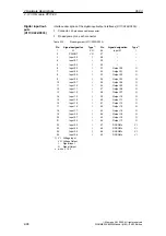
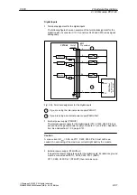
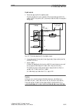
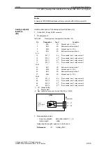
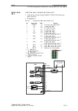
For specification of the external power supply, see Subsection 2.12.3,
page 2-101.
S
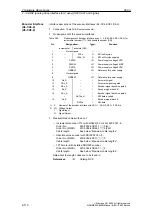
Connecting cable: The required connecting cables (ribbon cables) must be
provided by the user
S
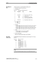
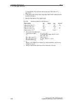
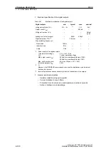
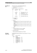
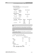
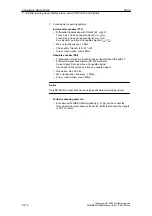
Electrical specification of the digital inputs:
Table 2-20
Electrical specification of the digital inputs
Digital outputs
min.
typical
max.
nominal
Voltage at high level (V
hi)
15V
1)
30V
24V
Input current I
IN
at VU
hi
2mA
–
15mA
–
Voltage at low level (V
lo)
–30V
–
+5V
0V
Signal delay time T
PHL
2)
0.5msec
–
3msec
–
S
Power supply of the digital inputs
1) typical output voltage:
V
CC
– I
OUT
<
R
ON
V
CC
:
Current operating voltage (P24OUT) at X111,
X222, X333: Pin 2
Max. output current I
OUT
:
500mA per pin
Max. short-circuit current:
4A (max. 100
m
sec, V
CC
= 24V)
Internal resistance R
ON
:
0.4
W
S
2)
Moreover, the PROFIBUS communication time and the application cycle time must
be taken into account.
S
Polarity reversal causes neither high level nor destruction of the inputs.
2 Hardware Descriptions

