06.03
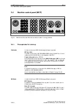
5.4 Machine control panel (MCP)
5-144
Siemens AG, 2003. All rights reserved
SINUMERIK 840Di Manual (HBI) – 06.03 Edition
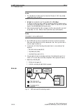
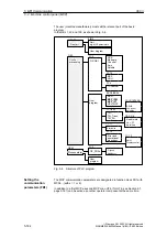
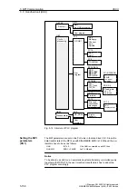
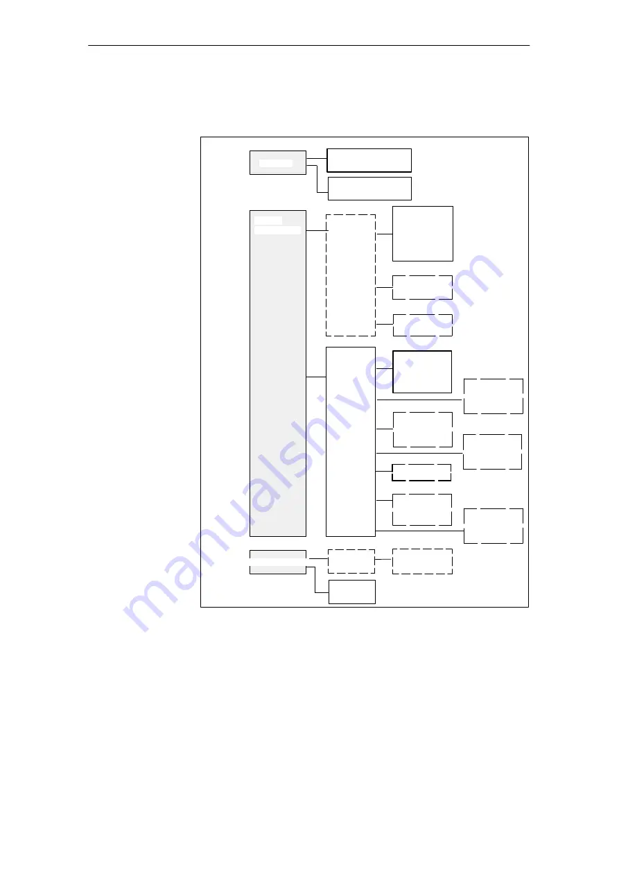
The user (machine manufacturer) must call the relevant part of the basic
program
in the OBs 1, 40 and 100, as shown in Fig. 5-6.
ÎÎÎÎÎ
ÎÎÎÎÎ
Process alarm
ÎÎÎ
ÎÎÎ
Cyclic
ÎÎÎÎ
processing
GP_PRAL
GP-OB 1
NCK
Mode grp.
Channel
Axis
Spindle
TOOLMAN
User
program
User
program
OB 40
OB 1
OB 100
G group
distributor
FC 14
FC 3
MCP,
HHU
FC 6
ASUB,
con. axes/
spindles
Read/ write
var., PI
services
FB 2/3/4
TM:
TM_Trans
TM_Dir
FC 7/8/22
ÎÎÎ
ÎÎÎ
Restart
FC 2
FC (9/15/16/18)
Error and
operational
messages
FC 10
HHU:
Display control
FC 13
User program
FB 1
Start:
e.g.
MCP parameters
FC 19/25/26
MCP:
MCP_IFM
MCP_IFT
HPU_MCP
Star/delta
FC 17
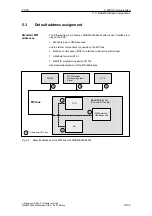
Fig. 5-6
Structure of PLC program
The MCP communication parameters are designated in function block FB1 with
MCPx... (with x = 1 or 2).
In addition to a first MCP, a second MCP or an HT 6 (for HT 6, see Section 5.7,
page 5-161) can be active as another operator component at the same time.
Setting the
communication
parameters (FB1)
5 MPI Communication

