06.03
10.5 Axes and spindles
10-317
Siemens AG, 2003. All rights reserved
SINUMERIK 840Di Manual (HBI) – 06.03 Edition
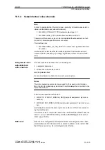
/FB/
Description of Functions, Basic Machine
A2 Various Interface Signals
Section: Interface signals to axis/spindle
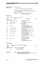
10.5.5
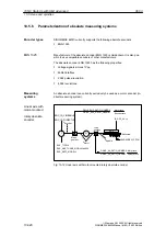
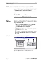
Parameterization of incremental measuring systems
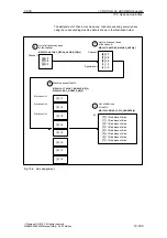
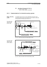
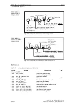
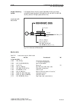
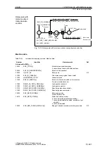
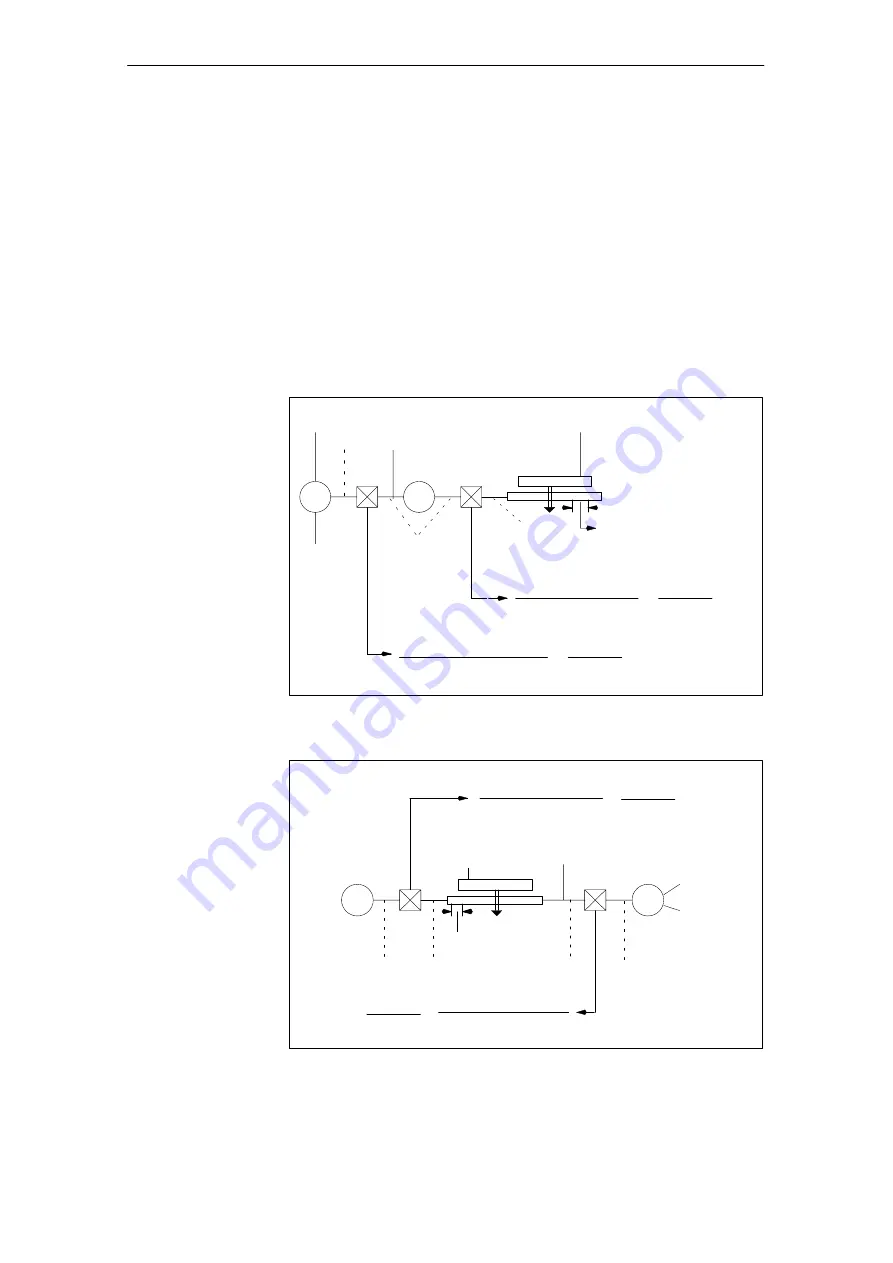
The diagrams below show the general possibilities of arranging a rotary
incremental measuring system with regard to motor and load, as well as the
resulting values for the appropriate machine data.
M
IS_ROT_AX=0
ÍÍÍÍÍ
Table
ENC_IS_LINEAR_=0
ENC_RESOL
F
DRIVE_AX_RATIO_NUMERA
DRIVE_AX_RATIO_DENOM
ENC_IS_DIRECT=0
LEADSCREW_PITCH
n
Encoder
Meas.
gearbox
nMotor
Load
gearbox
nSpindle
Ball screw
DRIVE_ENC_RATIO_NUMERA
DRIVE_ENC_RATIO_DENOM
Encoder revs
Motor revs
Spindle revs
Motor revs
=
Fig. 10-7 Linear axis with motor-mounted rotary encoder
M
IS_ROT_AX=0
ÍÍÍÍÍ
ÍÍÍÍÍ
Table
ENC_RESOL
F
DRIVE_ENC_RATIO_NUMERA
DRIVE_ENC_RATIO_DENOM
ENC_IS_DIRECT=1
LEADSCREW_PITCH
ENC_IS_LINEAR_=0
Load
gearbox
Meas.
gearbox
n
Spindle
n
Encoder
DRIVE_AX_RATIO_NUMERA
DRIVE_AX_RATIO_DENOM
Leadscrew
n
Spindle
n
Motor
Spindle revs
Motor revs
=
Encoder revs
Motor revs
=
ENC_TYPE=1
ENC_IS_LINEAR=0
ENC_RESOL
Fig. 10-8 Linear axis with machine-mounted rotary encoder
Rotary measuring
system
Linear axis with
rotary encoder
on the motor
Linear axis with
rotary encoder
on the machine
10 NC Start-Up with HMI Advanced

