06.03
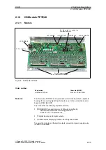
2.12 I/O Module PP72/48
2-95
Siemens AG, 2003. All rights reserved
SINUMERIK 840Di Manual (HBI) – 06.03 Edition
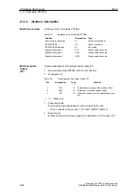
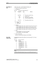
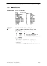
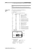
Interface description of the PROFIBUS DP interface (X2):
S
Connection:
9-pin SUB-D socket connector
S
Pin assignment.
Table 2-17
Pin assignment: PROFIBUS DP (X2)
Pin
Designation
Type
1)
Function
1
–
–
–
2
–
–
–
3
RxD/TxD-P
B
Receive/transmit data P (B line)
4
RTS
O
Request to Send
5
DGND
VO
Data reference potential (M5V)
6
VP
VO
Power supply voltage plus (P5V)
7
–
–
–
8
RxD/TxD-N
B
Receive/transmit data N (A line)
9
–
–
–
1) VO
Voltage Output
O
Output
B
Bi-directional
S
Connector
–
6ES7972-0BA40-0XA0; cable outlet 35
0
, without PG socket connector
–
6ES7972-0BB40-0XA0; cable outlet 35
0
, with PG socket connector
–
6ES7972-0BA11-0XA0; cable outlet 90
0
, without PG socket connector
–
6ES7972-0BB11-0XA0; cable outlet 90
0
, with PG socket connector
S
Cables:
–
6XV1830-0EH10; by the meter, non-trailable
–
6XV1830-3BH10; by the meter, trailable
S
Further technical data
Maximum possible data transmission rate: 12 Mbit/sec.
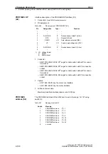
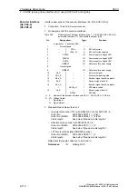
The PROFIBUS address of the ADI4 can be set in the range 1 to 127 using
switch S1.
Table 2-18
Meaning of switch S1
Switch
Meaning
1
PROFIBUS address:
2
0
= 1
2
PROFIBUS address:
2
1
= 2
3
PROFIBUS address:
2
2
= 4
4
PROFIBUS address:
2
3
= 8
5
PROFIBUS address:
2
4
= 16
6
PROFIBUS address:
2
5
= 32
7
PROFIBUS address:
2
6
= 64
8
not used
Notice
A newly set PROFIBUS address will only come into effect after power ON.
PROFIBUS DP
(X2)
PROFIBUS
address (S1)
2 Hardware Descriptions

