5 Configuring
11.92
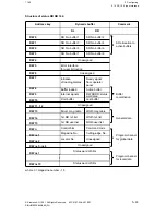
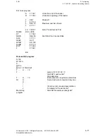
5.14 FB 155 Input via tape
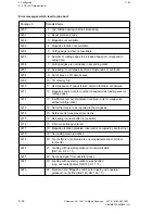
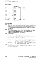
R34
DW 199 to
201
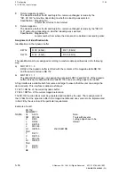
User 5
R35
DW 202 to
204
User 6
R36
DW 205 to
207
User 7
R38
DW 211 to
213
SST DW 32
high byte
bit pattern (8 bits)
R39
DW 214 to
216
SST DW 32
low byte
bit pattern (8 bits)
R40
DW 217 to
219
SST DW 33
high byte
bit pattern (8 bits)
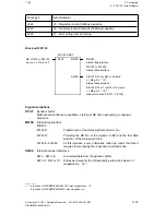
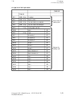
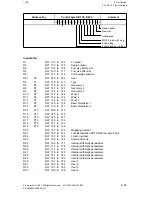
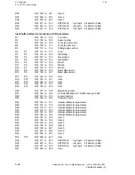
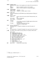
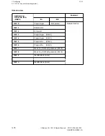
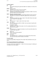
Input buffers listed in accordance with R parameters
R1
DW 100 to
102
T number
R2
DW 103 to
105
Duplo number
R3
DW 106 to
108
Tool size before slot
R4
DW 109 to
111
Tool size after slot
R5
DW 112 to
114
Cutting-edge number
R6
P1
DW 115 to
117
Type
R7
P2
DW 118 to
120
Geometry 1
R8
P3
DW 121 to
123
Geometry 2
R9
P4
DW 124 to
126
Geometry 3
R10
P5
DW 127 to
129
Wear 1
R11
P6
DW 130 to
132
Wear 2
R12
P7
DW 133 to
135
Wear 3
R13
P8
DW 136 to
138
Basic dimension 1
R14
P9
DW 139 to
141
Basic dimension 2
R15
P11
DW 142 to
144
User
R16
P12
DW 145 to
147
User
R17
P13
DW 148 to
150
User
R18
P14
DW 151 to
153
User
R19
P15
DW 154 to
156
User
R20
DW 157 to
159
Magazine number
R21
DW 160 to
162
Tool identification SST DW32 low byte 8 bits
R22
DW 163 to
165
Locator number
R23
DW 166 to
168
Command code
R24
DW 169 to
171
Internal arithmetic parameters
R25
DW 172 to
174
Internal arithmetic parameters
R26
DW 175 to
177
Internal arithmetic parameters
R27
DW 178 to
180
Internal arithmetic parameters
R28
DW 181 to
183
Internal arithmetic parameters
R29
DW 184 to
186
Internal arithmetic parameters
R30
DW 187 to
189
User 1
R31
DW 190 to
192
User 2
R32
DW 193 to
195
User 3
R33
DW 196 to
198
User 4
R34
DW 199 to
201
User 5
R35
DW 202 to
204
User 6
R36
DW 205 to
207
User 7
R37
P10
DW 208 to
210
User
R38
DW 211 to
213
SST DW 32
high byte
bit pattern (8 bits)
R39
DW 214 to
216
SST DW 33
low byte
bit pattern (8 bits)
R40
DW 217 to
219
SST DW 33
high byte
bit pattern (8 bits)
R41
DW 220 to
222
User
5–66
© Siemens AG 1991 All Rights Reserved 6FC5 197-0AA40-1BP1
SINUMERIK 840/880 (PJ)

