11.92
6 NC Programming
6.1 Loading cycle L940
6
NC Programming
As from Version 3 of the tool management, the message texts of the tool management cycles
are stored in the file named DIAL.TTA. The user must load this file into the user memory.
This file is already included in the link lists of the given examples.
6.1
Loading cycle L940
The loading cycle L 940 is used for loading via tape.
The data of the tools are written into the R parameters of the NC from tape (for R parameter
assignments please refer to Section 10.4).
The loading cycle determines the number of the active PLC. The relevant NC channel is
entered in DW 3 of DB 135 by the loading cycle.
The number of the M function, which is required for the loading procedure, is read in the
machine data.
The error number entered in DR 10 of DB 135 in the case of an error, is evaluated by the
loading cycle L 940 and output as an error message on the screen.
6.2
Tool changing cycle L06
The tool changing cycle L 06 is called for the tool change.
It provides the M function M 06 (for milling machines) and provides the compensation address
of the first cutting edge of the selected tool. It reads this address in the R parameter R 101.
6.3
Unloading cycle L947 (SINUMERIK 880/880 GA2 only)
Together with FB 120, L947 generates a part program for selected tools or whole magazines
with which it is possible to load the tools at another machine with the same data (see also
FB 120).
While it is active, L947 generates the tempory file L948 in which the loading blocks are
generated individually and the NC block numbers are updated. Once a loading block has been
processed, it is copied into the loading program. L948 is deleted when L947 is completed.
The magazine back-up function is set in the initial setting. Additional functions can be specified
using the configured displays (see also the accompanying operating examples). The user
determines the program number.
The function block checks whether the program arleady exists. An error message is output if
an error occurs and the program is ended.
FB 120 is triggered by the M function defined by the user after the part program frame has
been generated. FB 120 accesses the tool data for the user. If an error occurs in FB 120, an
error number is entered in R parameter R41.
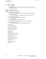
If an error occurs in the PLC, L947 deletes L948 and goes into programmed stop.
© Siemens AG 1991 All Rights Reserved 6FC5 197-0AA40-1BP1
6–1
SINUMERIK 840/880 (PJ)

