11.92
2 Description of Functions
2.1.1 Overview
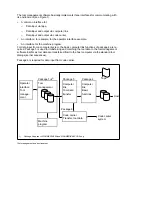
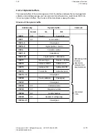
The data blocks for the superordinate areas are determined as follows and are established
either permanently or using machine data of FB 117 "EINR-MAG".
Tool list, DB 151 to 156
(set up permanently by FB 117)
•
Tool identifications, DB 151 to 153
Specification of the tool status with regard to tool life/end of number of pieces, tool size
etc.
•
Ident number, DB 154 and 155
The eight-decade ID No. (also known as tool number or T No.) for identification of the
tools is stored here.
•
Duplo number, DB 156
The duplo numbers serve to distinguish identical tools (also called sister tools if ID Nos.
are identical). The duplo numbers may be four-decade numbers at the most.
User area, DB 157 to max. 163
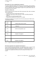
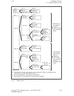
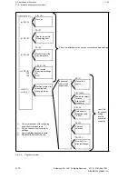
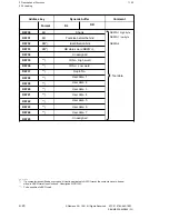
Figure 2.5 shows an example of a magazine/turret table with one user DB, that is DB 157.
Users can create up to seven data blocks in this area to suit their specific requirements. The
required number of the data blocks has to be specified by the user in PLC machine data 2002
for PLC 1 or in PLC machine data 2102 for PLC 2, depending on whether the tool manage-
ment is implemented in PLC 1 or PLC 2
2)
.
Reference list, max. 9 DBs
The reference list contains the addresses (D Nos.) under which the offsets of the individual
cutting edges of the tools are stored in the TO memory. A maximum of nine cutting edges
and/or their offsets can be handled. The width of the reference list has to be specified in PLC
machine data 2003 for PLC 1 and/or in PLC machine data 2103 for PLC 2 (DB61)
2)
. The DB
number (initial DB No.) that marks the beginning of the reference list depends on the width of
the user area.
Location specification for replacement tools if T=location
If a location is addressed via the T call in the part program for turning machines and the turret
is equipped with replacement tools (the submagazine-specific bits must be set in DB 64!) a
data block (DB 167 in Fig. 2.5) is also generated. If one or more tools (replacement tools) are
available for a tool on the turret, the package software enters the reference to the replacement
tool.
Basic dimension, maximum width up to 9 DBs
•
Tool adapters, DB 168 to 171
1)
This data block area is provided for the case that the tool adapters are on different pitch
circles on a turret. In this case, the distance (radius) from the turret center (of the
individual pitch circle) has to be entered as a reference dimension. In the case of turrets
with only one pitch circle, the basic dimension is irrelevant since the basic dimension is
the same for all locations in the magazine table and can therefore be entered directly in
the TO memory for all tool offsets.
_______
1)
The data blocks mentioned here refer to Figure 2.5 (example). They differ depending on the number of user
blocks, the width of the reference list and whether replacement locations are used.
2)
PLC 2 applies to SINUMERIK 880/880 GA2 only
© Siemens AG 1991 All Rights Reserved 6FC5 197-0AA40-1BP1
2–5
SINUMERIK 840/880 (PJ)


