01.91
2 Description of Functions
2.1.2 Interface and program overview
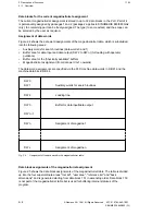
Functional area "Basic functions"
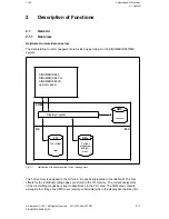
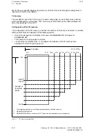
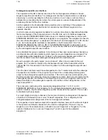
The basic functions are used for providing the locator and magazine numbers as well as
various user commands for the tool called in the part program at the user interface to the
machine program. The basic functions have both read and write access to the tool-specific
user interface. The basic functions include various search algorithms which can be selected
via the parameter assignments of the basic functions by means of the FB machine data words
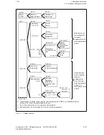
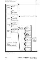
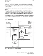
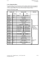
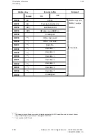
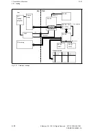
and bits in DB 61 and 64 (refer also to Figures 2.7 and 2.8, Program Overview; possible
parameter assignments are described in detail in Section 10).
Functional area "Data handling"
Two types of functions are available for data handling:
1.
"Internal functions"; initialization within each package via data words, flags and PLC
machine data words and bits.
2.
Function blocks assigned by the user for user-oriented data handling.
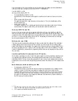
Re 1 Internal functions
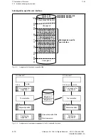
The "internal functions" are intended for the management and input/output to and from
the data buffers and manage the TO memory for the data input and output of tool data
via tape, code carrier and host computer (see Figures 2.7 and 2.8).
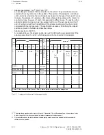
Re 2 User-oriented data handling
The function blocks to be parameterized by the user for user-oriented data handling
include the functions Tool life and Monitoring of number of pieces, Tool size presetting
for size one for all magazine locations and those functions providing the tools for the
pending part program.
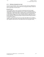
User function blocks
The functions supporting the machine program are to be initialized by the user and to be
integrated into the user-specific sequential controller for the machine control. The machine
control/machine program is adapted to the machine configuration and the strategy selected,
which, in turn, is selected according to the spectrum of parts to be machined, the tool
insertion/removal procedures and, if necessary, the tool sorts.
The respective functions are ”Neutral tool search”, ”Search for empty location” with or without
presetting the tool size, ”Data transfer magazine table
tool buffer”, ”Direction selection” and
”Provision of addresses in the TO memory” for the tool offsets of the tool inserted (see
Figures 2.7 and 2.8).
© Siemens AG 1991 All Rights Reserved 6FC5 197-0AA40-1BP1
2–11
SINUMERIK 840/880 (PJ)


