10 Data fields
11.92
10.2 NC machine data
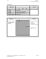
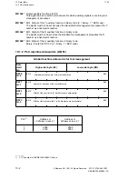
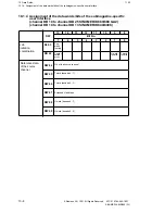
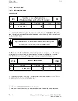
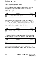
MD 540* Output auxiliary functions to PLC
This signal has to be set for all channels, for which auxiliary signals concerning tool
management are output.
MD 544* Bit 4 Output of the T auxiliary function in binary code (0 = binary, 1 = BCD code)
The signal must not be set because the standard tool management processes the T
number as a fixed-point number.
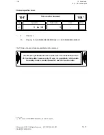
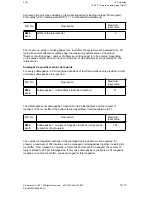
MD 544* Bit 5 Output of the D auxiliary function in binary code
The signal must not be set since the standard tool management processes the D
number as a fixed-point number.
MD 544* Bit 6 Output of the H auxiliary function in binary code
Binary if routed to FB 133 (0 = binary, 1 = BCD code)
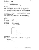
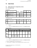
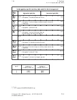
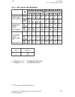
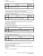
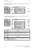
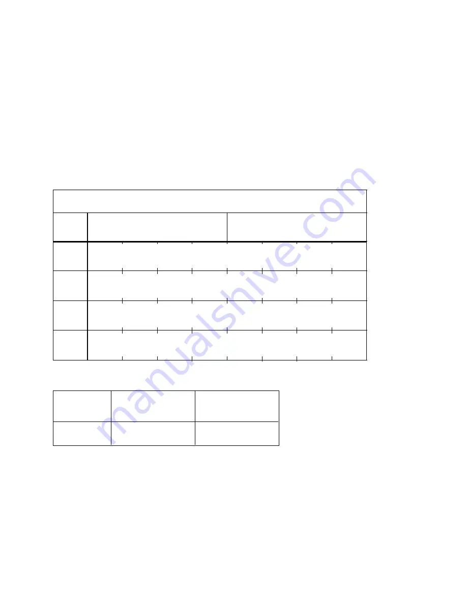
10.1.2 PLC machine data words (DB 61)
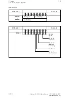
DW 2
m+2
Data
word
No.
High-order byte (DL)
Global machine data words for tool management
Bit 15
Low-order byte (DR)
Bit 15
Bit 15
Bit 15
Bit 0
Bit 0
Bit 0
Bit 0
DW 0
m+0
DW 1
m+1
DW 3
m+3
Initial address (data word) of the tool buffer area
Number of locations of the tool buffer area
Width of the user list (0 to 7 data blocks are permissible)
Width of the reference list (1 to 9 data blocks are permissible)
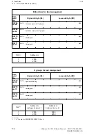
PLC
1)
Address m
< Software Version 6.1
Address m
Software Version 6.1
1
2
2000
2100
2000
2250
_______
1)
PLC 2 applies to SINUMERIK 880/880 GA2 only
10–2
© Siemens AG 1991 All Rights Reserved 6FC5 197-0AA40-1BP1
SINUMERIK 840/880 (PJ)

