02.93
10 Data fields
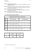
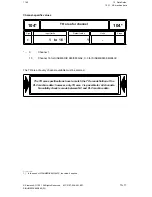
10.2.2 PLC machine data words (DB 61)
DW 72
m+ 72
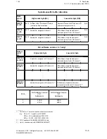
Special positioning
MD No.
Description
Specification of the H group to be used for special positioning. If the H group of an H function
included in the part program and the H group defined here are identical, the 16 low-order bits
of the H word are entered in data word DW 75 of the submagazine-specific user interface of
the current channel DB.
Note:
The H function for special positioning can only be programmed in connection with a tool
request in the part program. If they are stated separately, the job is rejected with an error
message ( error in part program).
During machining without special positioning, the PLC machine data is to be preset with a
value not equal to that of the H groups of the part program.
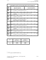
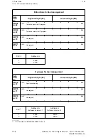
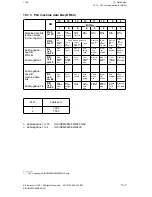
Machine data for extensions/options
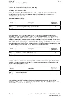
At present, the PLC machine data words MD 2075 to MD 2077 and 2102 to 2133 for the
definition of spindles and local tool buffer areas are used.
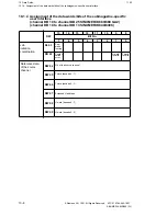
Definition of spindles:
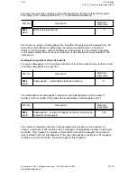
Up to six spindles can be defined by specifying the spindle number, the NC channel to which it
is assigned and the data word address within the tool buffer. The channel number of the first
spindle is user-selectable. The channel number of the second spindle is automatically assigned
to the channel immediately following the channel of the first spindle. The data word addresses
of the spindles are defined for the end of the tool buffer generated via PLC machine data MD
2000 and MD 2001.
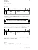
Definition of local tool buffers:
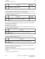
Local tool buffers are areas assigned to a channel. If, for example, two spindles are imple-
mented and the identification numbers of the tools loaded are identical, the tool in spindle 1
should not be reported as being found in a T call concerning spindle 2. In such a case, a
check would be made whether the tool had been found in a local buffer. If this were the case,
the tool would be regarded as found only if the channel calling and the channel of the local tool
buffer were defined as being identical (defined by MD 2075).
For defining local tool buffer areas, the data word addresses of the spindles are not defined
contiguously and not at the end of the tool buffer: If, for example, data word 12 is specified for
spindle 1 and data word 15 for spindle 2, the areas DW 13 and DW 14 are also defined as
local buffer and, if DW 15 is not the last data word of the buffer defined by MD 2000 and MD
2001, the remaining area is also declared local buffer.
Tool buffers defined as local buffers are found by the tool selection only if the channel of the
requesting part program and the assigned channel of the tool buffer are identical.
© Siemens AG 1991 All Rights Reserved 6FC5 197-0AA40-1BP1
10–15
SINUMERIK 840/880 (PJ)

