Installation
42
9229 0020 176 0B
2019-04-02
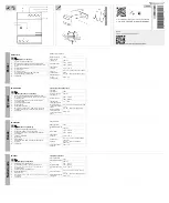
Carefully brush the contact surfaces of the conductor bars cross-wise with a steel
brush until they are bright and wipe off any residue using a clean cloth.
After cleaning, very lightly grease the bright contact surfaces with acid-free Vaseline
(e. g. Shell-Vaseline 8420) and screw together immediately.
Screw-in depths in the upper and lower terminals
Fig. 55
Screw-in depths
Connecting the main conductor
Mounting busbars
Adjust the conductor bars in such a way that, before fastening, they lie flat easily and
fit the holes on the contact surfaces of the upper and lower terminal.
Corresponding to the rated current strength, use M12 or M8 screws and nuts -
strength class 8.8 - and the appropriate spring elements and washers for the con-
nection of the conductor bars.
When tightening the screws, hold the nuts against the tightening torque with a suit-
able screwdriver or socket spanner.
Rated voltage
U
r
kV
12
24
Rated short-circuit breaking current
I
sc
kA
12.5 - 25
Rated normal current
I
r
A
800 - 1250
Terminal thread
M12
2 x M8
Upper terminal (A)
mm
20 ±1
Lower terminal (B)
mm
Note
For vacuum circuit-breakers with connecting bars, it is recommended to use the
stainless steel screws or non-magnetisable stainless steel screws included in the
supplementary equipment.
Fig. 56
Screw-in depths in the upper and lower termi-
nals
Fig. 57
Installing busbars (angled). Example for
1 250 A
Summary of Contents for SION 3AE6113-0
Page 10: ...Transport storage and packing 10 9229 0020 176 0B 2019 04 02 Blank page ...
Page 44: ...Installation 44 9229 0020 176 0B 2019 04 02 Blank page ...
Page 50: ...Operation 50 9229 0020 176 0B 2019 04 02 Blank page ...
Page 54: ...Maintenance 54 9229 0020 176 0B 2019 04 02 Blank page ...
Page 58: ...58 9229 0020 176 0B 2019 04 02 Blank page ...


