background image

SIPART DR19
C73000-B7474-C140-06

45

Kurzanleitung

Programmregler

Es werden hier nur die speziellen Angaben zum Programmregler gemacht; die 
Bedienung zum Parametrieren und Konfigurieren und weitere Anzeigemöglichkei-
ten bleiben davon unberührt! Eingriffe über Binärsignale sind nicht beschrieben.

5.3

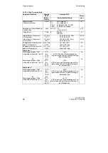
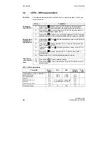
CLPA - Clock-Parameter

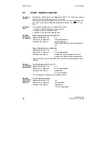
Einstellung der programmspezifischen Parameter und Funktionen für den Pro-
grammregler/Programmgeber.

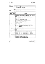
(14)

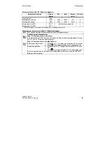
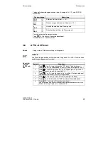
Meldeleuchte

Programmsollwert w

über CB abgeschaltet, Uhr hält

(15)

Meldeleuchte

Sollwert intern (Uhr hält, Sollwert verstellbar)

(17)

Meldeleuchte

Ausgeführtes Programm 

->1=PR1
->2=PR2

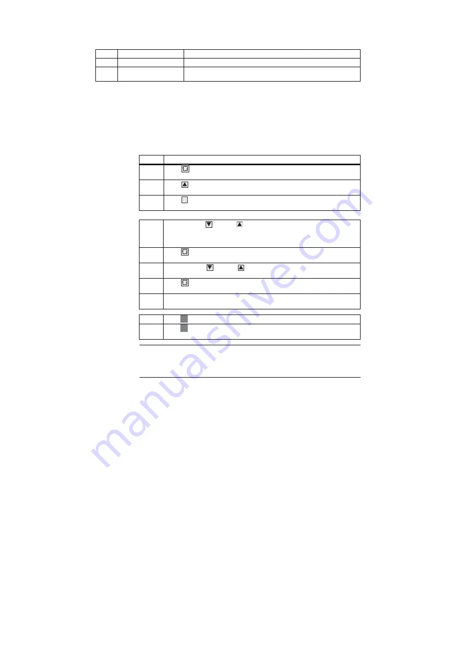
Schritt

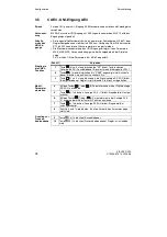
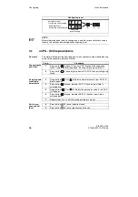
Vorgehen

1

Taste 

(6) ca. 5 s lang drücken bis "PS" blinkt, Taste loslassen - 

Anzeige "onPA" (Auswahlebene). Blockiert, wenn Binärsignal bLPS=1.

2

Taste 

(8) mehrmals drücken bis "CLPA" angezeigt wird (Auswahle-

bene). Blockiert, wenn Binärsignal bLS=1.

3

Taste 

(9) ca.3 s lang drücken bis Digitalanzeige SP-W (2) blinkt 

(Konfigurierebene). Regler ist jetzt blockiert, letztes y wird  gehalten.

4

Mit den Tasten 

(7) oder 

(8) Parameternamen in der Digitalanzeige 

SP-W (2) auswählen.

Schnellgang

: Erst Richtungstaste, dann zusätzlich zweite Verstelltaste 

betätigen. 

5

Taste 

(6) 1x drücken, Anzeige PV-X (1) blinkt, Eingabefeld ist umge-

schaltet.

6

Mit den Tasten 

(7) oder 

(8) Parameterwert in der Anzeige PV-X 

(1) ändern.  

Schnellgang:

 siehe Schritt 4.

7

Taste 

(6) 1x drücken, Anzeige SP-W (2) blinkt Eingabefeld ist 

zurückgeschaltet.

8

Schritte 4 bis 7 wiederholen, bis alle erforderlichen Parameter einge-
stellt sind.

9

Taste 

(13) 1x drücken (Auswahlebene).

10

Taste 

(13) 1x drücken (Prozessbedienebene) Regler ist in Handbe-

trieb.

+

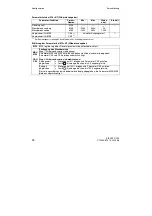
HINWEIS

Für ein funktionsfähiges Programm müssen mindestens die Parameter PrSE, 
CLFO, t...und A... in der Clock-Parameterliste CLPA festgelegt worden sein; 
Strukturschalter, S43=2, S23=8 (CB="HIGH")

Funktion

Einstieg in 
die CLPA-
Funktion

Parameter 
auswählen 
und ändern

Ausstieg zur 
Prozessbe-
dienebene

Summary of Contents for SIPART DR19

Page 1: ...Kurzanleitung Quick Reference Edition 12 2001 SIPART DR19 Kompaktregler Compact controller 6DR1900 6DR1901 4 ...

Page 2: ......

Page 3: ...SIPART DR19 C73000 B7474 C140 06 3 s SIPART DR19 6DR1900 6DR1901 4 Kurzanleitung Seite 5 Quick Reference Page 49 ...

Page 4: ...Gewähr übernehmen Die Angaben in dieser Anleitung werden regelmäßig überprüft und notwendige Korrekturen sind in den nachfolgenden Auflagen enthalten Für Verbesserungsvorschläge sind wir dankbar Siemens AG 1995 Technische Änderungen bleiben vorbehalten DANGER indicates an immenently hazardous situation which if not avoided will result in death or serious inury WARNING indicates a potentially hazar...

Page 5: ...Übersicht 5 2 Bedienen und Beobachten 7 2 1 Bedienbeispiele 8 2 2 Betriebs und Fehlermeldungen 10 3 Konfigurieren 11 3 1 onPA Online Parameter 12 3 2 oFPA Offline Parameter 14 3 3 StrS Strukturschalter 15 3 4 CAE1 UNI Eingang AE1 29 3 5 CAE3 UNI Engang AE3 32 3 6 AdAP Adaption starten 35 3 7 AdAP Adaption beenden 36 3 8 APSt All Preset 37 4 Blockschaltbild 38 4 1 Eingangschaltungen 39 4 2 Ausgangs...

Page 6: ...SIPART DR19 6 C73000 B7474 C140 06 Übersicht Kurzanleitung ...

Page 7: ...wert steigt 9 Umschalttaste Hand Automatik oder Enter Taste zum Einstieg von der Auswahlebene in die Konfigurierebene 10 Meldeleuchte y extern Betrieb 11 Meldeleuchte Handbetrieb 12 Meldeleuchten der y Binärausgänge beim S Regler 13 Umschalttaste Sollwert intern extern oder Exit Taste zum Ausstieg aus der Konfigurier und Auswahlebene in die Prozessbedienebene 14 Meldeleuchte Computer mit wext abge...

Page 8: ...er S87 und S88 WENN w angezeigt wird UND wenn der Regler auf Intern Betrieb DANN ist eine w Verstel lung möglich HINWEIS Diese Sollwertänderung ist nicht möglich z B bei Handbetrieb mit Sollwertnach führung x Tracking Externbetrieb bei Folgeregler S1 usw oder WENN y angezeigt wird DANN ist eine w Verstellung nicht mög lich Beispiel 1 Anzeige SP W Lösung Sollwert w 2 w x OUT Y SP W Dauerlicht OUT Y...

Page 9: ...N ist eine y Änderung möglich Stellglied Stellglied zu auf auf zu HINWEIS Eine y Änderung ist nur dann möglich wenn Meldeleuchte y extern Betrieb 10 aus d h kein y extern Betrieb kein Nachführ Sicherheits oder Blockier betrieb Beispiel 3 y Änderung Lösung Umschaltung Automatik Handbetrieb Dauerlicht Taste 9 1x drücken Taste 9 1x drücken Automatikbetrieb 11 Handbetrieb schaltet w Display mit um 11 ...

Page 10: ...zeige PV X 1 angezeigt werden Über oder Unterschreitung des Anzeigebereichs Analogsignalüberwachung von z B Eingang 3 Zeichen an 3 Stelle angesprochen Überwachung der CPU nach Zuschalten der Hilfsenergie CPU defekt EEPROM defekt Signalumformermodul UNI Option auf Steckplatz 1 nicht gesteckt Signalumformermodul Option auf Steckplatz 3 nicht gesteckt Liste von Meldungen ...

Page 11: ... die Bedien und Anzeigefront durchge führt Zunächst wird die Funktion der Bedien und Anzeigefront von der Prozessbedien ebene in die Auswahlebene umgeschaltet Dort werden die Parameterlisten die Strukturschalterliste oder die Inbetriebnahmefunktionen ausgewählt Nach einem weiteren Wechsel in die Konfigurierebene können die Parameter der ausgewählten Liste angezeigt und verändert werden Funktionen ...

Page 12: ...ken Digitalanzeige SP W 2 blinkt Konfigurierebene 3 Mit den Tasten 7 oder 8 Parameternamen in der Digitalan zeige SP W 2 auswählen 4 Taste 6 1x drücken Anzeige PV X 1 blinkt Eingabefeld ist umgeschaltet 5 Mit dem Tasten 7 oder 8 Parameterwert in der Anzeige PV X 1 ändern 6 Taste 6 1x drücken Anzeige SP W 2 blinkt Eingabefeld ist zurückgeschaltet 7 Schritte 3 bis 7 wiederholen bis alle erforderlich...

Page 13: ...00 10 00 100 0 9984 2992 10 0 100 0 110 0 110 0 110 0 110 0 1 000 5 000 0 100 9984 oFF 0 0 Auto 0 0 0 0 0 0 0 0 s 1 1 s s Stellwertanfang YA YE Stellwertende Periodendauer Heizen y Stellzeit auf Periodendauer Kühlen y Stellzeit zu YA YE tP tM 10 0 10 0 oFF 0 100 oFF 0 100 110 0 110 0 1 000 1 000 5 0 105 0 1 000 1 000 s s Stellimpulspause Stellimpluslänge tA tE 20 20 6001 6001 200 200 ms ms Filterz...

Page 14: ...an zeige SP W 2 auswählen 5 Taste 6 1x drücken Azeige PV X 1 blinkt Verstelltasten 7 8 sind auf PV X umgeschaltet 6 Mit den Tasten 7 oder 8 Parameterwert in der Anzeige PV X 1 ändern 7 Taste 6 1x drücken Anzeige SP W 2 blinkt Eingabefeld ist zurückgeschaltet 8 Schritte 4 bis 7 wiederholen bis alle erforderlichen Parameter einge stellt sind 9 Taste 13 1x drücken Auswahlebene 10 Taste 13 1x drücken ...

Page 15: ...10 0 110 0 110 0 110 0 110 0 110 0 110 0 10 0 0 0 10 0 20 0 30 0 usw bis 110 0 1 1 1 1 1 1 Schritt Vorgehen 1 Taste 6 ca 5 s lang drücken bis PS blinkt Taste loslassen Anzeige onPA Auswahlebene Blockiert wenn Binärsignal bLPS 1 2 Taste 8 mehrmals drücken bis StrS angezeigt wird Auswahl ebene Blockiert wenn Binärsignal bLS 1 3 Taste 9 ca 3 s lang drücken bis Digitalanzeige SP W 2 blinkt Konfigurier...

Page 16: ...Int Ext Umschaltung für Leitsystemkopplung 1 1 ab Softwarestand A7 S2 Ausgangsstruktur 0 1 2 3 K Ausgang S Ausgang Zweipunktregler mit 2 Ausgängen Heizen Kühlen S Ausgang Dreipunktschrittregler für motorische Antriebe interne Rückführung S Ausgang Dreipunktschrittregler für motorische Antriebe externe Rückführung S3 Netzfrequenzunterdrückung 0 1 50 Hz 60 Hz S4 Standardeingang AE1 I mV R P T Messum...

Page 17: ... 2 Grad Celsius Grad Fahrenheit Kelvin S8 Eingangssignal AE2 Steckplatz 2 und Messumformerstörungsmel dung 0 1 2 3 I 0 bis 20 mA oder U R P T ohne MUF I 0 bis 20 mA oder U R P T mit MUF I 4 bis 20 mA oder U ohne MUF I 4 bis 20 mA oder U mit MUF S9 Eingangssignal AE3 Steckplatz 1 und Messumformerstörungsmel dung 0 1 2 3 4 5 6 7 I 0 bis 20 mA oder U R P T ohne MUF I 0 bis 20 mA oder U R P T mit MUF ...

Page 18: ... Leiter Anschluss 6 7 Widerstandsgeber mit R 600 Ω Widerstandsgeber mit R 2 8 kΩ S11 Thermoelementtyp AE3 Steckplatz 2 mit UNI Modul nur wirksam bei S10 1 2 0 1 2 3 4 5 6 7 8 9 10 Typ L Typ J Typ K Typ S Typ B Typ R Typ E Typ N Typ T Typ U beliebiger Typ ohne Linearisierung Radizierung AE1 bis AE3 nein ja S12 S13 S14 AE1 0 1 AE2 0 1 AE3 0 1 Zuweisung von x1 x2 x3 yN yR z nach AE1A bis AE3A 0 AE1 A...

Page 19: ...2 S33 S34 S100 CB 0 1 2 3 4 5 6 7 8 He 0 1 2 3 4 5 6 7 N 0 1 2 3 4 5 6 7 Si 0 1 2 3 4 5 6 7 P 0 1 2 3 4 5 6 7 8 tS2 0 1 2 3 4 5 6 7 yBL 0 1 2 3 4 5 6 7 yBL 0 1 2 3 4 5 6 7 bLb 0 1 2 3 4 5 6 7 bLS 0 1 2 3 4 5 6 7 bLPS 0 1 2 3 4 5 6 7 PU1 0 1 2 3 4 5 6 7 8 tSH3 0 1 2 3 4 5 6 7 1 PU Low Programm 1 bei PrSE P1 P2 PU High Programm 2 bei PrSE P1 P2 2 ab Softwarestand B6 Reset Funktion bei S1 5 3 ab Soft...

Page 20: ...fall 0 1 letztes wi Sicherheits Sollwert SH1 S46 Nachführen von wi oder SH1 SH2 SH3 SH4 auf den wirksam Soll wert w wi SH1 bis SH4 0 1 2 ja nein nein nein ja ja bei S1 1 S47 Wirksinn bezogen auf xd w x 0 1 normal Kp 0 reversiert Kp 0 S48 D Glied Aufschaltung 0 1 2 3 4 xd x x1 z Wirksinn gegen x Aufschaltung auf Stellgrösse y z Wirksinn mit x Aufschaltung auf Stellgrösse y S49 Wahl der Adaption 0 1...

Page 21: ...ja statisch mit keine Umschaltung Handbetrieb ja ja dynamisch mit ja ja dynamisch ohne 1 ab Softwarestand A7 S53 Iy Abschaltung bei Nachführbetrieb nur K Regler 0 1 ohne mit S54 Stellgrössenbegrenzung YA YE 0 1 Nur im Automatikbetrieb wirksam In allen Betriebsarten wirksam S55 Stellgrössenanzeige 0 1 2 3 Reglerausgang y Stellungsrückmeldung yR Splitrange y1 y2 bei Zweipunktregler Heizen Kühlen kei...

Page 22: ...20 mA x1 0 bis 20 mA x1 4 bis 20 mA xd 50 0 bis 20 mA xd 50 4 bis 20 mA 10 11 12 13 14 15 16 17 y1 0 bis 20 mA y1 4 bis 20 mA y2 0 bis 20 mA y2 4 bis 20 mA Ab Softwarestand B5 1 y1 0 bis 20 mA 1 y1 4 bis 20 mA 1 y2 0 bis 20 mA 1 y2 4 bis 20 mA S58 Zuweisung y BA1 BA2 BA7 Relais BA8 Relais 0 1 2 3 y y y y y y y y Hinweis S58 hat Vorrang vor S59 bis S75 Struktur schalter Stellung Funktion ANALOGAUSG...

Page 23: ...7 8 Hinweis Wenn BA1 2 bzw BA7 8 durch S57 mit y belegt sind ist keine Mehrfachzuweisung möglich Zuweisung verschiedener Steuersignale auf einen Binärausgang bewirkt ODER Funktion Zuweisung der Zeitschiene Statusmeldungen des Programmreglers auf Binärausgänge Grundgerät Steckplatz 3 Grundgerät keine BA1 BA2 BA3 BA4 BA5 BA6 BA7 BA8 Relais Relais S70 S71 S72 S73 S74 S75 Clb1 0 1 2 3 4 5 6 7 8 Clb2 0...

Page 24: ...max S87 Anzeige und Einstellung der Grenzwerte A1 bis A4 in der Prozess bedienebene Anzeige auf Parameter Signalisierung der ange SP W 2 1 verstellbar sprochenen Grenzwerte L1 bis L4 1 0 1 2 3 4 5 6 nein nein A1 A2 A3 A4 nein nein A3 A4 z B für S1 5 nein nein nein für S1 1 oder 5 A3 A4 nein A3 A4 z B für S1 5 A1 A2 A3 A4 nein A1 A2 A3 A4 A3 A4 ja A3 A4 z B für S1 5 A1 A2 A3 A4 ja A1 A2 A3 A4 Hinwe...

Page 25: ... um A1 bis A4 verlängert wer den 1 wirksames wi 2 nicht wirksames wi bei Festwertregler mit zwei oder fünf Sollwerten S88 mit S1 3 Reihenfolge auf den Anzeigen PV X 1 und SP W 2 wenn S1 3 Reihenfolge auf der Anzeige SP W Anzeige PV X I II III IV I II III IV 0 1 2 3 wv y xv xv wv y w1 xv xv x1 wv y wvE xv xv xv wv y wvE w1 xv xv xv x1 x LED 0 0 0 1 0 0 0 1 w LED 1 0 0 5 1 1 0 0 5 1 1 Dauerlicht 0 5...

Page 26: ...e um A1 bis A4 verlängert wer den 1 in xxx x 2 Meldeleuchten w aus 3 Meldeleuchte w aus Anzeige SP W dunkel S88 mit S1 5 Reihenfolge auf den Anzeigen PV X 1 und SP W 2 wenn S1 5 Reihenfolge auf der Anzeige SP W Anzeige PV X Analoganzeige I II III IV I II III IV I II III IV 0 1 2 3 4 5 6 7 w y x x x w y x1 x x x w y x x x w y x1 x x x w y wpz x x x w y x1 wpz x x x w w wpz x LED 0 0 0 5 0 5 0 5 0 5...

Page 27: ...s w Programmregler Startposition Reset Zustand bei K Regler YS bei S Regler letztes y S91 Optische Signalisierung nach Netzwiederkehr 0 1 ohne Blinken der PV X und SP W Anzeige mit Blinken der PV X und SP W Anzeige S92 Serielle Schnittstelle Steckplatz 4 0 1 1 2 3 ohne serielle Schnittstelle mit serieller Schnittstelle mit Verriegelung durch RC mit serieller Schnittstelle mit Verriegelung durch CB...

Page 28: ... Bit s 300 Bit s S95 Querparity 0 1 gerade even ungerade odd S96 Längsparity Lage 0 1 2 ohne nach ETX vor ETX S97 Längsparity 0 1 normal invertiert S98 Stationsnummer 0 bis 125 0 bis 125 ab Softwarestand A9 S99 Zeitüberwachung CB ES 0 1 bis 25 oFF 1 s bis 25 s S100 siehe Strukturschalter S34 Struktur schalter Stellung Funktion SERIELLE SCHNITTSTELLE ...

Page 29: ...ssen Anzeige onPA Auswahlebene Blockiert wenn Binärsignal bLPS 1 2 Taste 8 mehrmals drücken bis CAE1 angezeigt wird Auswahle bene 3 Taste 9 ca 3 s lang drücken bis die Digitalanzeige SP W 2 blinkt Konfigurierebene Regler ist jetzt blockiert letztes y wird gehalten 4 Mit den Tasten 7 oder 8 Parameternamen in der Digitalanzeige SP W 2 auswählen 5 Taste 6 1x drücken Anzeige PV X 1 blinkt Eingabefeld ...

Page 30: ...r Cr1 aufrufen Taste 9 so lange drücken bis 0 00 angezeigt wird Leitungswiderstand wird dabei selbständig abgeglichen Parameter Mr1 zeigt gemessenen Leitungswiderstand an MP1 MP1 legt die Lage des Dezimalpunktes für den Messbereich fest MA1 ME1 Festlegung des Messbereichs bei Themoelemente oder Pt100 Direktanschluss S5 1 2 3 4 5 Die Einstellung erfolgt direkt in ºC ºF K Werten S7 0 1 2 Soll der ge...

Page 31: ...wert MP1 MP1 legt die Lage des Dezimalpunktes für den Messbereich fest MA1 ME1 CA1 CE1 Festlegung des Messbereichs Weg 1 Widerstandswerte sind bekannt Parameter MA1 und ME1 aufrufen und bekannte Widerstandswerte eingeben Parame ter CA1 und CE1 bleiben unberücksichtigt Weg 2 Widerstandswerte sind nicht bekannt Anfangswert abgleichen Stellglied auf 0 bringen und Parameter CA1 aufrufen Taste 9 so lan...

Page 32: ...eige onPA Auswahlebene Blockiert wenn Binärsignal bLPS 1 2 Taste 8 mehrmals drücken bis CAE3 angezeigt wird Auswahle bene Blockiert wenn Strukturschalter S9 4 3 Taste 9 ca 3 s lang drücken bis die Digitalanzeige SP W 2 blinkt Konfigurierebene Regler ist jetzt blockiert letztes y wird gehalten 4 Mit den Tasten 7 oder 8 Parameternamen in der Digitalanzeige SP W 2 auswählen 5 Taste 6 1x drücken Anzei...

Page 33: ...hliessen Parameter Cr3 aufrufen Taste 9 so lange drücken bis 0 00 angezeigt wird Leitungswiderstand wird dabei selbstständig abgeglichen Parameter Mr3 zeigt gemes senen Leitungswiderstand an MP3 MP3 legt die Lage des Dezimalpunktes für den Messbereich fest MA3 ME3 Festlegung des Messbereichs bei Thermoelement oder Pt100 Direktanschluss S10 1 2 3 4 5 Die Einstellung erfolgt direkt in ºC ºF K Werten...

Page 34: ...ert MP3 MP3 legt die Lage des Dezimalpunktes für den Messbereich fest MA3 ME3 CA3 CE3 Festlegung des Messbereichs Weg 1 Widerstandswerte sind bekannt Parameter MA3 und ME3 aufrufen und bekannte Widerstandswerte eingeben Parameter CA3 und CE3 bleiben unberücksichtigt Weg 2 Widerstandswerte sind nicht bekannt Anfangswert abgleichen Stellglied auf 0 bringen und Parameter CA3 aufrufen Taste 9 solange ...

Page 35: ...ner Regelkreis erfolgen Die Adaption wird zweckmässigerweise im Automatikbetrieb des Reglers gestartet und beendet Nach Abschluss der Adaption regelt der Regler dann im Automatikbetrieb nach den ermittelten Parametern weiter HINWEIS Wird die Adaption im Handbetrieb gestartet und beendet gibt der Regler nach der Adaption einen Stellwert y aus der eine möglichst kleine Regeldifferenz bewirkt Die Onl...

Page 36: ...ung Meldeleuchte AdAPT 16 aus Bedien und Anzeigefront Prozessbedienebene Betriebsart des Reglers Automatikbetrieb Regler regelt nach den neuen Reglerparame tern Meldeleuchte AdAPT 16 aus Bedien und Anzeigefront Prozessbedienebene Betriebsart des Reglers Handbetrieb der ausgegebene Stellwert y bewirkt eine möglichst kleine Regeldifferenz Nach Umschalten in den Automatikbetrieb wird mit den neuen Re...

Page 37: ...Einstellungen werden auf Werkseinstellung gesetzt Die APSt Funktion kann nicht rückgängig gemacht werden Schritt Vorgehen 1 Taste 6 ca 5 s lang drücken bis PS blinkt Taste loslassen Anzeige onPA Auswahlebene Blockiert wenn Binärsignal bLPS 1 2 Taste 8 mehrmals drücken bis APSt angezeigt wird Auswahle bene Blockiert wenn Binärsignal bLS 1 3 Taste 9 ca 3 s lang drücken bis no erscheint Konfiguriereb...

Page 38: ... Rel 5BE Steckplatz 3 S92 bis S99 4 2 4 7 4 8 4 3 Steckplatz 4 SES 5 V M N L BA2 BA1 oy oy AA ly 0 4 bis 20 mA oder 19 V 50 mA I Optionen Grund einstellungen S1 bis S3 Analogeingänge S4 bis S21 Bestückung Steckplatz 3 S22 Binäreingänge S23 bis S41 Sollwertführung S42 bis S46 Regelalgorithmus S47 bis S49 Y Umschaltung S50 bis S54 Y Anzeige S55 bis S56 Analogausgang S57 Schaltausgänge S58 Binärausgä...

Page 39: ...stwertregler mit fünf Sollwerten S1 2 Folge SPC Regler mit Int Ext Umschaltung wi1 INT CB 0000 w wi2 0000 x x x1 c1 x2 c2 x3 c3 x1 x2 x3 PID yH y ya w x xd wi1 INT 0000 w 0000 x x x1 c1 x2 c2 x3 c3 x1 x2 x3 PID yH y ya w x xd INT SH4 CB PU SH3 CB PU SH2 CB PU SH1 CB PU wi1 INT CB 0000 w wES 0000 x x x1 c1 x2 c3 x1 x2 PID yH y ya w x xd x3 wEA 2 3 S93 0 1 wE c4 we c5 ...

Page 40: ...grammgeber wvi INT CB 0000 wv wES 0000 xv vist x1 x2 PID yH y ya w x xd x3 wEA 2 3 S93 0 1 w v x2 c5 x1 c5 x2 v wv vE vA vA wi INT CB 0000 x1 wES 0000 w x1 yH y w x xd wEA 2 3 S93 0 1 wE c4 we c5 Dw Dw INT CB 8 9 U I S57 2 3 Dw Dw AA H 0000 w 0000 x x x1 c1 x2 c2 x3 c3 x1 x2 PID yH y ya w x xd A U I AA S57 2 3 x3 wi1 INT CB Reset Clb1 bis Clb6 INT A wp A H N Si ...

Page 41: ... 6 7 S1 61 Festwertregler mit einem Sollwert Leitsystemkopplung S1 71 Folgeregler ohne Int Ext Umschaltung Leitsystemkopplung 1 ab Softwarestand A7 0000 w 0000 x x1 x2 PID yH y ya w x xd x x1 c1 x2 c3 wi1 x3 0000 w 0000 x x1 x2 PID yH y yA w x xd x x1 c1 x2 c3 wE c4 we c5 x3 wEA ...

Page 42: ...2 Dreipunktschritt S Regler interne Rückführung S2 3 Dreipunktschritt S Regler externe Rückführung w xd 0 1 U I S55 0 Iy AA y y000 S57 I P 0 4 bis 20 mA 8 9 10 11 U I y I P 0 4 bis 20 mA y000 Y2 Y1 y000 12 13 tP tM Heizen Kühlen S57 S55 0 S55 2 y2 y1 Dy Dy Y2 Y1 y Dy Dy tP tM S55 1 Dy Dy y000 tA tE M y yR Ty E a S55 1 Dy Dy y000 tA tE M y yR Ty E a tP tM ...

Page 43: ...enzwerte geprüft Sind die Grenzen überschritten so wird der Zeitablauf angehalten und auf den nachgeführten wi umgeschaltet Mit Unterschreiten der hold Grenzwerte wird wie der auf Programmsollwert zurückgeschaltet Die Uhr läuft wieder Manuelles Umschalten ist jederzeit möglich nop Eingabe erfolgt wenn ein Wechsel einer Statusmeldung während der Ram penlaufzeit nötig ist Der analoge Ausgangswert wi...

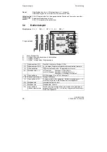
Page 44: ...1 Restzeit im Intervall 6 Umschalttaste SP W Anzeige 2 und PV X Anzeige 1 7 8 Sollwertverstellung wi Sollwert fällt steigt 9 Umschalttaste H A In Hand wird die Uhr angehalten Mit der Verknüpfung Int H wird das Programm in die Startposition zurückgesetzt 10 Meldeleuchte y extern Betrieb Uhr hält 11 Meldeleuchte Handbetrieb Uhr hält 13 Umschalttaste Sollwert intern extern Bei Int wird die Uhr angeha...

Page 45: ...gnal bLS 1 3 Taste 9 ca 3 s lang drücken bis Digitalanzeige SP W 2 blinkt Konfigurierebene Regler ist jetzt blockiert letztes y wird gehalten 4 Mit den Tasten 7 oder 8 Parameternamen in der Digitalanzeige SP W 2 auswählen Schnellgang Erst Richtungstaste dann zusätzlich zweite Verstelltaste betätigen 5 Taste 6 1x drücken Anzeige PV X 1 blinkt Eingabefeld ist umge schaltet 6 Mit den Tasten 7 oder 8 ...

Page 46: ...10 bis 110 von dA dE nop 0 0 Analogwerte an den Intervall enden im Programm 2 A 01 2 bis A 05 2 10 bis 110 von dA dE nop 0 0 Programm 1 Binärausgangssignal CLb1 während der Intervalle 1 bis 10 1 01 1 bis 1 10 1 1 PE 1 Lo Hi x PE x Status der Binärausgänge am Programmende und am Programmanfang in der Startposition Lo bis Binärausgangssignal CLb6 während der Intervalle 1 bis 10 bis 6 01 1 bis 6 10 1...

Page 47: ...rt intern extern bzw DDC Betrieb StrS S23 S42 dA Parameter w x Digitalanzeige Einstellung Anfangswert oFPA Seite 14 dE Parameter w x Digitalanzeige Einstellung Endwert oFPA Seite 14 dP Parameter w x Digitalanzeige Einstellung des Dezimal punktes oFPA Seite 14 H Betriebsart Handbetrieb des Reglers BA Meldung Regler in Handbetrieb StrS S61 HA Parameter Hysterese der Alarme A1 bis A4 oFPA Seite 14 He...

Page 48: ...pe anhalten StrS S100 wEA Eingang Externer Sollwert als Analogsignal S1 2 3 4 und S93 2 3 Eingangsschaltungen Seite 39 wES Eingang Externer Sollwert über Schnittstelle S1 2 3 4 7 und S93 0 1 2 3 Y1 Parameter Splitrange links Kühlen Zweipunktregler S2 1 oFPA Seite 14 Y2 Parameter Splitranger rechts Heizen Zweipunktregler S2 1 oFPA Seite14 YA Parameter Stellwertbegrenzung Anfang onPA Seite 12 S54 YE...

Page 49: ...9 2 Operating and Monitoring 51 2 1 Operating Examples 52 2 2 Operating and Error Messages 54 3 Configuring 55 3 1 onPA Online parameters 56 3 2 oFPA Offline parameters 58 3 3 StrS Configuring switches 59 3 4 CAE1 UNI Input AI1 73 3 5 CAE3 UNI Input AI3 76 3 6 AdAP Start Adaption 79 3 7 AdAP End Adaptation 80 3 8 APSt All Preset 81 4 Block Diagram 82 4 1 Input Circuits 83 4 2 Control Structures 86...

Page 50: ...SIPART DR19 50 C73000 B7474 C140 06 Overview Quick Reference ...

Page 51: ...d value increase decrease or button decrease setpoint 9 Switchover button Hand Auto or Enter button for accessing the selection level in the configuration level 10 Signal lamp y external operation 11 Signal lamp hand operation 12 Signal lamps for the y digital outputs with S controller 13 Switchover button internal external setpoint or Exit button to return from configuring and selection levels to...

Page 52: ...S87 and S88 IF w is displayed AND the controller is in internal mode THEN w can be modified NOTE The setpoint cannot be modified in for example manual mode with setpoint tracking x tracking external mode on slave controller S1 ect or IF y is displayed THEN w cannot be modified Example 1 SP W indicator Method setpoint w 2 w x OUT Y SP W permanent light OUT Y SP W actuating value y 2 Press button 6 ...

Page 53: ...dified actuating actuating unit unit down up up down NOTE The value of y can only be modified if the signal lamp y external mode 10 is not on i e the controller must not be in y external tracking safety or blocking mode Example 3 Modification of y Method Tog gling between manual and automatic modes permanent light press button 9 1x press button 9 1x automatic mode 11 manual mode w display switched...

Page 54: ...displayed on the PV X 1 dig ital indicator Value too large small for indicator Analog signal monitoring e g input 3 character in 3rd digit position tripped CPU monitoring following power up CPU defective EEPROM defective UNI signal conditioning module optional in slot 1 not installed Signal conditioning module optional in slot 3 not installed List of messages ...

Page 55: ...e front panel of the controller The function of the front panel is first changed from process operation level to selection level from where the parameter lists configuring switch lists or com missioning functions can be selected After then switching to the configuring level the parameters of the selected list can be displayed and modified functions can be executed 6 5 s 13 9 13 Process control lev...

Page 56: ...ton 9 once digital indicator SP W 2 flashes configuring level 3 Using buttons 7 or 8 Select parameter names from SP W 2 digital indicator 4 Press button 6 once indicator PV X 1 flashes input field is switched over 5 Using buttons 7 or 8 Modify the parameter value in the PV X 1 indicator 6 Press button 6 once indicator SP W 2 flashes input field is switched back 7 Repeat steps 3 to 7 until all desi...

Page 57: ...84 2992 10 0 100 0 110 0 110 0 110 0 110 0 1 000 5 000 0 100 9984 off 0 0 Auto 0 0 0 0 0 0 0 0 s 1 1 s s Start of manip variable scale YA YE Full scale of manip variable Heating period y positioning time open Cooling period y positioning time closed YA YE tP tM 10 0 10 0 off 0 100 off 0 100 110 0 110 0 1 000 1 000 5 0 105 0 1 000 1 000 s s Actuating pulse interval Length of actuating pulse tA tE 2...

Page 58: ... W 2 digital indicator 5 Press button 6 once indicator PV X 1 flashes Adjustment but tons 7 8 operate on PV X 6 Using buttons 7 or 8 Modify parameter values in the PV X 1 indicator 7 Press button 6 once indicator SP X 2 flashes input field is switched back 8 Repeat steps 4 to 7 until all desired parameters are set 9 Press button 13 once selection level 10 Press button 13 once process control level...

Page 59: ...0 110 0 110 0 110 0 110 0 110 0 110 0 10 0 0 0 10 0 20 0 30 0 etc up to 110 0 1 1 1 1 1 1 Step Procedure 1 Press button 6 about 5 sec until PS flashes Release button onPA selection level displayed Blocked if digital signal bLPS 1 2 Press button 8 several times until StrS is displayed selection level Blocked if digital signal bLS 1 3 Press button 9 about 3 sec until digital indicator SP W 2 flashes...

Page 60: ...er with one setpoint1 Slave controller without int ext switchover 1 1 as of software version 3 S2 Output structure 0 1 2 3 K output S output Two step controller with 2 outputs heating cooling S output Three step controller for motorized drives internal feedback S output Three step controller for motorized drives external feedback S3 Mains frequency suppression 0 1 50 Hz 60 Hz S4 Standard input AI1...

Page 61: ... S5 or S10 1 2 3 4 5 0 1 2 Degrees Celsius Degrees Fahrenheit Degress Kelvin S8 Input signal AI2 slot 2 and transmitter fault signal 0 1 2 3 I 0 20 mA or U R P T without MUF I 0 20 mA or U R P T with MUF I 4 20 mA or U without MUF I 4 20 mA or U with MUF S9 Input signal AI3 slot 1 and transmitter fault signal 0 1 2 3 4 5 6 7 I 0 20 mA or U R P T without MUF I 0 20 mA or U R P T with MUF I 4 20 mA ...

Page 62: ...ion 6 7 Resistance transmitter with R 600 Ω Resistance transmitter with R 2 8 kΩ S11 Thermocouple type AI3 slot 2 with UNI module only effective if S10 1 2 0 1 2 3 4 5 6 7 8 9 10 Type L Type J Type K Type S Type B Type R Type E Type N Type T Type U Any type without linearization Take square roof of AI1 to AE3 no yes S12 S13 S14 AI1 0 1 AI2 0 1 AI3 0 1 Allocation of x1 x2 x3 yN yR z to AI1A to AI3A...

Page 63: ...100 CB 0 1 2 3 4 5 6 7 8 He 0 1 2 3 4 5 6 7 N 0 1 2 3 4 5 6 7 Si 0 1 2 3 4 5 6 7 P 0 1 2 3 4 5 6 7 8 tS2 0 1 2 3 4 5 6 7 yBL 0 1 2 3 4 5 6 7 yBL 0 1 2 3 4 5 6 7 bLb 0 1 2 3 4 5 6 7 bLS 0 1 2 3 4 5 6 7 bLPS 0 1 2 3 4 5 6 7 PU1 0 1 2 3 4 5 6 7 8 tSH3 0 1 2 3 4 5 6 7 1 PU Low Programm 1 with PrSE P1 P2 PU High Programm 2 with PrSE P1 P2 2 as of software version B6 reset function when S1 5 3 as of sof...

Page 64: ...t SH1 S46 Tracking of wi or SH1 SH2 SH3 SH4 to actual setpoint w wi SH1 to SH4 0 1 2 yes no no no yes yes if S1 1 S47 Direction of action in relation to xd w x 0 1 Normal Kp 0 Reversed Kp 0 S48 Connection of D element 0 1 2 3 4 xd x x1 z direction of action against x conn to manipipulated variable y z direction of action with x conn to manipulated variable y S49 Choice of adaptation 0 1 2 No adapt...

Page 65: ...o switchover manual operation yes yes dynamic with yes yes dynamic without 1 as of software version A7 S53 Iy shutdown in tracking mode K controller only 0 1 Without With S54 Limiting of manipulated variable YA YE 0 1 Only effective in automatic mode Effective in all modes S55 Manipulated variable display 0 1 2 3 Controller output y Position feedback yR Split range y1 y2 with two point controller ...

Page 66: ... to 20 mA x1 0 to 20 mA x1 4 to 20 mA xd 50 0 to 20 mA xd 50 4 to 20 mA 10 11 12 13 14 15 16 17 y1 0 to 20 mA y1 4 to 20 mA y2 0 to 20 mA y2 4 to 20 mA As of software version B5 1 y1 0 to 20 mA 1 y1 4 to 20 mA 1 y2 0 to 20 mA 1 y2 4 to 20 mA S58 Allocation y DO1 DO2 DO7 relay DO8 relay 0 1 2 3 y y y y y y y y Note S58 has priority over S59 to S75 Config switch Setting Function ANALOG OUTPUT DIGITA...

Page 67: ... If DO1 2 or DO7 8 have been allocated y by S57 duplicated alloca tion is not possible Allocation of various control signals to a digital output effects an OR function Time bus status signals Allocation of digital signals of the program controller to digital outputs Basic unit Slot 3 Basic unit none DO1 DO2 DO3 DO4 DO5 DO6 DO7 DO8 relay relay S70 S71 S72 S73 S74 S75 Clb1 0 1 2 3 4 5 6 7 8 Clb2 0 1...

Page 68: ...4 0 1 2 A3 max A4 min A3 min A4 min A3 max A4 max S87 Display and setting of limit values A1 to A4 in the process control level Indicator Parameter Signalling of violated limit SP W 2 1 adustable values via L1 to L4 1 0 1 2 3 4 5 6 no no A1 A2 A3 A4 no no A3 A4 for S1 05 no no no for S1 1 or 5 A3 A4 no A3 A4 for S1 5 A1 A2 A3 A4 no A1 A2 A3 A4 A3 A yes A3 A4 for S1 5 A1 A2 A3 A4 yes A1 A2 A3 A4 No...

Page 69: ... using S87 the display sequence can be extended by A1 to A4 1 Effective wi 2 Ineffective wi for fixed value controller with two or five setpoints S88 mit S1 3 Sequence on indicators PV X 1 and SP W 2 if S1 3 Sequence on indicator SP W Indicator PV X I II III IV I II III IV 0 1 2 3 wv y xv xv wv y w1 xv xv x1 wv y wvE xv xv xv wv y wvE w1 xv xv xv x1 x LED 0 0 0 1 0 0 0 1 w LED 1 0 0 5 1 1 0 0 5 1 ...

Page 70: ...sing S87 the display sequence can be extended by A1 to A4 1 in xxx x 2 Signal lamp w off 3 Signal lampw off Indicator SP W blank S88 mit S1 5 Sequence on indicators PV X 1 and SP W 2 if S1 5 Sequence on Indicator indicatorSP W PV X Analog indicator I II III IV I II III IV I II III IV 0 1 2 3 4 5 6 7 w y x x x w y x1 x x x w y x x x w y x1 x x x w y wpz x x x w y x1 wpz x x x w w wpz x LED 0 0 0 5 ...

Page 71: ...controller start position reset state YS with K controller last y with S controller S91 Optical signalling following return of power 0 1 Without PV X and SP W indicators flashing With PV X and SP W indicators flashing S92 Serial interface slot4 0 1 1 2 3 Without serial interface With serial interface with interlock of RC With serial interface with interlock of CB 2 With serial interface without in...

Page 72: ... Bit s 300 Bit s S95 Vertical parity 0 1 Even Odd S96 Longitudinal parity position 0 1 2 None After ETX Before ETX S97 Longitudinal parity 0 1 Normal Inverted S98 Station number 0 to 125 0 to 125 as of software version A9 S99 Time monitoring CB ES 0 1 to 25 oFF 1 s to 25 s S100 See structure switch S34 Config switch Setting Function SERIAL INTERFACE ...

Page 73: ... Release button onPA selection level displayed Blocked if digital signal bLPS 1 2 Press button 8 several times until CAE1 is displayed selection level 3 Press button 9 about 3 sec until digital indicator SP W 2 flashes configuring level Controller now blocked and last value of y retained 4 Using buttons 7 or 8 Select parameter names in the SP W 2 digital indicator 5 Press button 6 once indicator P...

Page 74: ...00 in two wire circuit Method 1 line resistance is known Select Mr1 parameter and enter known line resistance Cr1 parameter is ignored Cr1 Method 2 line resistance unknown Short circuit Pt100 at point of measurement Select Cr1 parameter Press button 9 until 0 00 is displayed Line resistance is then trimmed automatically Mr1 shows line resistance measured MP1 MP1 defines the position of the decimal...

Page 75: ...es Min Max Factory setting Eng unit Decimal point Start of scale value Full scale value MP1 MA1 ME1 _ 1999 1999 9999 9999 0 0 100 0 Ω Ω Calibrated value for MA1 Calibrated value for ME1 CA1 1 CE1 1 present output value present output value MP1 MP1 defines the position of the decimal point for the measuring range MA1 ME1 CA1 CE1 Definition of measuring range Method 1 resistance values are known Sel...

Page 76: ...lease button onPA selection level displayed Blocked if digital signal bLPS 1 2 Press button 8 several times until CAE1 is displayed selection level Blocked if configuring switch S9 4 3 Press button 9 about 3 sec until digital indicator SP W 2 flashes configuring level Controller now blocked and last value of y retained 4 Using buttons 7 or 8 Select parameter names in the SP W 2 digital indicator 5...

Page 77: ...point of measurement Select Cr3 parameter Press button 9 until 0 00 is displayed Line resistance is then trimmed automatically Mr1 shows line resistance measured MP3 MP3 defines the position of the decimal point for the measuring range MA3 ME3 Definition of measuring range with themocouples or directly connected Pt100s S10 1 2 3 4 5 The values are entered directly in ºC ºF K S7 0 1 2 If the select...

Page 78: ...3 1 present output value present output value MP3 MP3 defines the position of the decimal point for the measuring range MA3 ME3 CA3 CE3 Definition of measuring range Method 1 resistance values are known Select MA3 and ME3 parameters and enter known resistance values CA3 and CE3 parameters are ignored Method 2 resistance values unknown Calibrate start of scale value Set control element to 0 and sel...

Page 79: ...d loop or manual mode open loop It is best to start and end adaptation in automatic mode After completing the adaptation the controller then continues to operate in automatic mode according to the determined parameters NOTE If adaptation is started and ended in manual mode then after adaptation the controller outputs a manipulated variable y that causes as small a control differ ence as possible T...

Page 80: ...tion and monitoring front process control level Controller operating mode automatic mode the controller operates according to the new control parameters Signal lamp AdAPT 16 off Operation and monitoring front process control level Controller operating mode manual mode the output manipulated value y causes as small a control difference as possible After switching to automatic mode the controller op...

Page 81: ...to their original factory settings The APSt function can not be undone Step Procedure 1 Press button 6 about 5 sec until PS flashes Release button onPA selection level displayed Blocked if digital signal bLPS 1 2 Press button 8 several times until APSt is displayed selection level Blocked if digital signal bLS 1 3 Press button 9 for about 3 sec until no appears configuring level Controller is bloc...

Page 82: ... 2DI 2DO R el 5DI Slot 3 S92 to S99 4 2 4 7 4 8 4 3 Slot 4 SES 5 V M N L DO2 DO1 oy oy AO ly 0 4 to 20 mA or 19 V 50 mA I Options Basic settings S1 to S3 Analog inputs S4 to S21 Configuration of slot 3 S22 Digital inputs S23 to S41 Setpoint tracking S42 to S46 Control algorithm S47 to S49 Y switchover S50 to S54 Y indicator S55 to S56 Analog output S57 Switching output S58 Digital outputs S59 to S...

Page 83: ...oint controller with five setpoint values S1 2 Slave SPC controller with internal external switchover wi1 INT CB 0000 w wi2 0000 x x x1 c1 x2 c2 x3 c3 x1 x2 x3 PID yH y ya w x xd wi1 INT 0000 w 0000 x x x1 c1 x2 c2 x3 c3 x1 x2 x3 PID yH y ya w x xd INT SH4 CB PU SH3 CB PU SH2 CB PU SH1 CB PU wi1 INT CB 0000 w wES 0000 x x x1 c1 x2 c3 x1 x2 PID yH y ya w x xd x3 wEA 2 3 S93 0 1 wE c4 we c5 ...

Page 84: ...ntroller program set station wvi INT CB 0000 wv wES 0000 xv vist x1 x2 PID yH y ya w x xd x3 wEA 2 3 S93 0 1 w v x2 c5 x1 c5 x2 v wv vE vA vA wi INT CB 0000 x1 wES 0000 w x1 yH y w x xd wEA 2 3 S93 0 1 wE c4 we c5 Dw Dw INT CB 8 9 U I S57 2 3 Dw Dw AO H 0000 w 0000 x x x1 c1 x2 c2 x3 c3 x1 x2 PID yH y ya w x xd A U I AO S57 2 3 x3 wi1 INT CB Reset Clb1 Clb6 INT A wp A H N Si ...

Page 85: ... 61 Fixed point controller with control system connection S1 71 Slave controller without Int Ext switchover control system connection 1 as of software version A7 0000 w 0000 x x1 x2 PID yH y ya w x xd x x1 c1 x2 c3 wi1 x3 0000 w 0000 x x1 x2 PID yH y yA w x xd x x1 c1 x2 c3 wE c4 we c5 x3 wEA ...

Page 86: ...controller S2 2 Three step controller internal feedback S2 3 Three step controller external feedback w xd 0 1 U I S55 0 Iy DO y y000 S57 I P 0 4 20 mA 8 9 10 11 U I y I P 0 4 20 mA y000 Y2 Y1 y000 12 13 tP tM Heating Cooling S57 S55 0 S55 2 y2 y1 Dy Dy Y2 Y1 y Dy Dy tP tM S55 1 Dy Dy y000 tA tE M y yR Ty E a S55 1 Dy Dy y000 tA tE M y yR Ty E a tP tM ...

Page 87: ...d limit value has been maintained If the limits have been violated the time sequence up to the violation is stopped and switched to the lead wi By falling short of the hold limit values it is reset to the program setpoint The clock is running Switching to manual mode is always possible nop operation input is done if intervals are occupied by status signals without spe cial analog occurance being r...

Page 88: ... 2 Time left in interval displayd in 1 6 Switchover button SP W display 2 and PV X display 1 7 8 Adjust setpoint wi Decrease increase setpoint 9 Switchover button H A The clock is stopped in manual mode The Int H logic operation resets the program 10 Signal lamp External y mode clock stopped 11 Signal lamp Manual mode clock stopped 13 Switchover button internal external setpoint With Int the clock...

Page 89: ...t 3 sec until digital indicator SP W 2 flashes configuring level Controller now blocked and last value of y retained 4 Using buttons 7 or 8 select parameter names in the SP W 2 digital indicator Quick step Press one button after the other and remaining on both the direction buttons the first pressed determines the direction parameters will be let out in block at a time 5 Press button 6 once indica...

Page 90: ...log values at end of interval in program 2 A 01 2 to A 05 2 10 to 110 of dA dE nop 0 0 Program 1 Digital output signal Clb1 during intervals 1 to 10 1 01 1 to 1 10 1 1 PE 1 Lo Hi x PE x status of the digital outputs at the end of the program and at the start of the program in the start position Lo to Digital output signal Clb6 during intervals 1 to 10 to 6 01 1 to 6 10 1 6 PE 1 Lo Hi x PE x status...

Page 91: ... DI Switchover between internal external setpoint StrS S23 S42 dA Parameter w x digital display setting of start of scale oFPA page58 dE Parameter w x digital display setting of full scale value oFPA page 58 dP Parameter w x digital display setting of decimal point oFPA page 58 H Operating mode Manual mode of controller DO Message Controller in manual mode StrS S61 HA Parameter Hysteresis of alarm...

Page 92: ...put External setpoint as analog signal S1 2 3 4 and S93 2 3 Input connections page 83 wES Input External setpoint via interface S1 2 3 4 7 and S93 0 1 4 5 Input connections page 83 Y1 Parameter Split range left cooling two position controller S2 1 oFPA page 58 Y2 Parameter Split range right heating two position controller S2 1 oFPA page 58 YA Parameter Lower limit of manipulated variable onPA page...

Page 93: ......

Page 94: ...d in the Federal Republic of Germany Siemens AG Bereich Automatisierungs und Antriebstechnik Geschäftsgebiet Prozessinstrumentierung und analytik D 76181 Karlsruhe Siemens Aktiengesellschaft E Siemens AG 1995 All rights reserved ...

Reviews: