SIPART DR19
C73000-B7474-C140-06
73
Quick Reference
Configuring
3.4
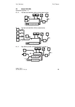
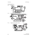
CAE1 - UNI Input AI1
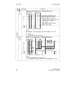
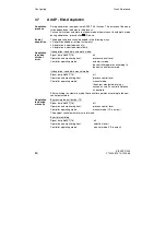
To select measuring ranges for the UNI (universal) input AI1 and trim if necessary.
The standard input and the input signal are selected with S4 and S5.
•
The selected measuring range is passed to the controller, where it is accessible
as AI1A as a standardized numerical value in the range 0 to 1. This variable can
be configured as required within the controller using configuring switches S15
to S20.
•
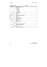
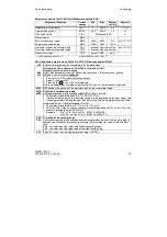
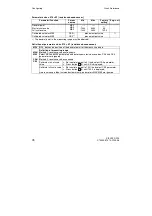
The measuring range of the UNI input is set using the parameters MA1, ME1,
MP1. The display range of the PV-X digital indicator is set independent of the
above using the Offline parameters dA, dE, dP.
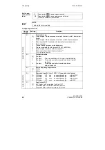
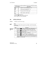
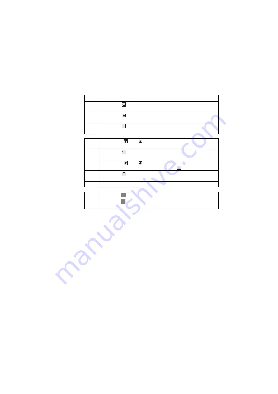
Step
Procedure
1
Press button
(6) about 5 sec until "PS" flashes. (Release button -
"onPA" (selection level) displayed. Blocked if digital signal bLPS=1.
2
Press button
(8) several times until "CAE1" is displayed (selection
level).
3
Press button
(9) about 3 sec until digital indicator SP-W (2) flashes
(configuring level). Controller now blocked and last value of y retained.
4
Using buttons
(7) or
(8). Select parameter names in the SP-W (2)
digital indicator.
5
Press button
(6) once, indicator PV-X (1) flashes, input field is
switched over.
6
Using buttons
(7) or
(8). Modify the parameter value in the PV-X
(1) indicator, or invoke a function using button
(9).
7
Press button
(6) once, indicator SP-W (2) flashes, input field is
switched back.
8
Repeat steps 4 to 7 until all desired parameters are set.
9
Press button
(13) once (selection level).
10
Press button
(13) once (process control level). Controller is in manual
mode.
Purpose
Requirement
Mode of
operation of
the UNIT
input
Access to
the CAE1
function
Set module
parameters
Exit to pro-
cess con-
trol level
Summary of Contents for SIPART DR19
Page 2: ......
Page 6: ...SIPART DR19 6 C73000 B7474 C140 06 Übersicht Kurzanleitung ...
Page 50: ...SIPART DR19 50 C73000 B7474 C140 06 Overview Quick Reference ...
Page 93: ......


