SIPART DR20
Project Planning Manual
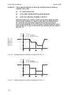
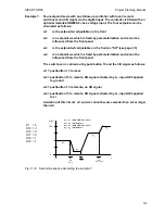
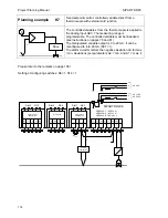
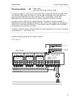
Example 7:
Four-setpoint mode with one follow-up controller with local / remote
switchover and CB signal via the digital input. The controller is fitted with an
optional module 6DR2800-8J as a voltage input. The four setpoints can be
simulated as follows:
w1
is the setpoint wi adjustable on the front
w2
is a setpoint wa which is fixed by parameterization and cannot be
influenced from the front panel
w3
is the setpoint wS adjustable on the front as "SH" (see page 33)
w4
is a setpoint we which is fixed by parameterization and cannot be
influenced from the front panel
The switchover is carried out by pushbutton 13 and the CB signal as follows:
w1 = pushbutton 13 to local
w2 = pushbutton 13 to remote, CB signal activated by L+, input AE3 applied
to ground
w3 = pushbutton 13 to remote, no CB signal
w4 = pushbutton 13 to remote, CB signal activated by L+, input AE3 applied
to L+
Limitation of this circuit: w1 and w3 cannot become smaller than w2 or larger
than w4.
S1 = 5
S10 = -1
S15 = 3
S17 = 0
S18 = 1
S19 = 1
100
0
w
1
w
2
w
3
w
4
INT
INT
CB
wE = 0
INT
INT
CB
wE = +24 V
CB
t
w (%)
w
1
= w
i
(adjustable on front)
w
2
= w
A
(parameter)
w
3
= w
S
(adjustable on front)
w
4
= w
E
(parameter)
Fig. 11/8
Setpoint response according to example 7
107

