SIPART DR20
Project Planning Manual
3. Technical
Description
3.1 Hardware
The SIPART DR20 process controller is of modular design and therefore easy to service and to
convert or retrofit. It consists of a standard controller in which additional option modules can be
inserted to extend the functions. These option modules are inserted into slots at the rear side of the
closed controller (see Fig. 2/2).
The standard controller contains two non-floating inputs for analog currents. Since other input
signals are sometimes to be processed or a floating condition is desired and the SIPART DR20
can also process three analog input signals simultaneously, two of the rear slots are designed for
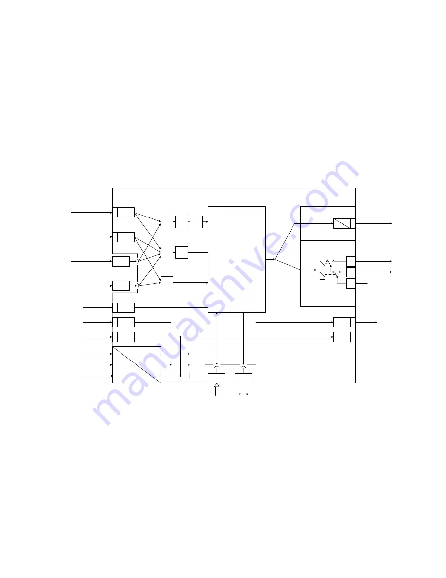
fitting with additional input modules. The arrangement of the fixed and optional input signal
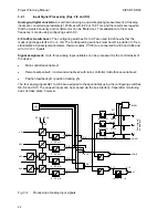
converters to the process signals is optional; the possibilities are shown in Fig. 3/1.
AE3
I
0/4 ... 20 mA
0/4 ... 20 mA
I
I - U - R - P - T
I - U - R - P - T
Options
AE4
AE2
2
AE1
1
x1
√
lin.
x2
wE
√
yR
yN
BE
3
L +
5
M
6
BE
20 V
M
L
N
PE
SES
GW
Options
BA
4
Front panel
with
microcontroller
EPROM and EEPROM
and
control and display
unit
M
7
BA
M
8
K: 6DR2004
S: 6DR2001
+
∆
y / Heating
K --> continous
U
I
Iy
-
∆
y / Cooling
0/4 ... 20 mA
y
10
8
9
Two-position/
Two channel or
Three-position step
L
Fig. 3/1 Functional diagram of SIPART DR20
13

