background image

Project Planning Manual 


SIPART DR20


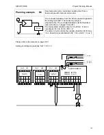
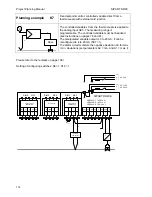
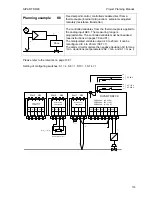
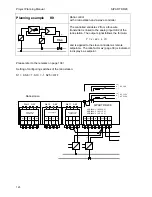
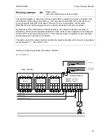
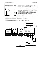
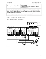
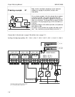
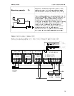
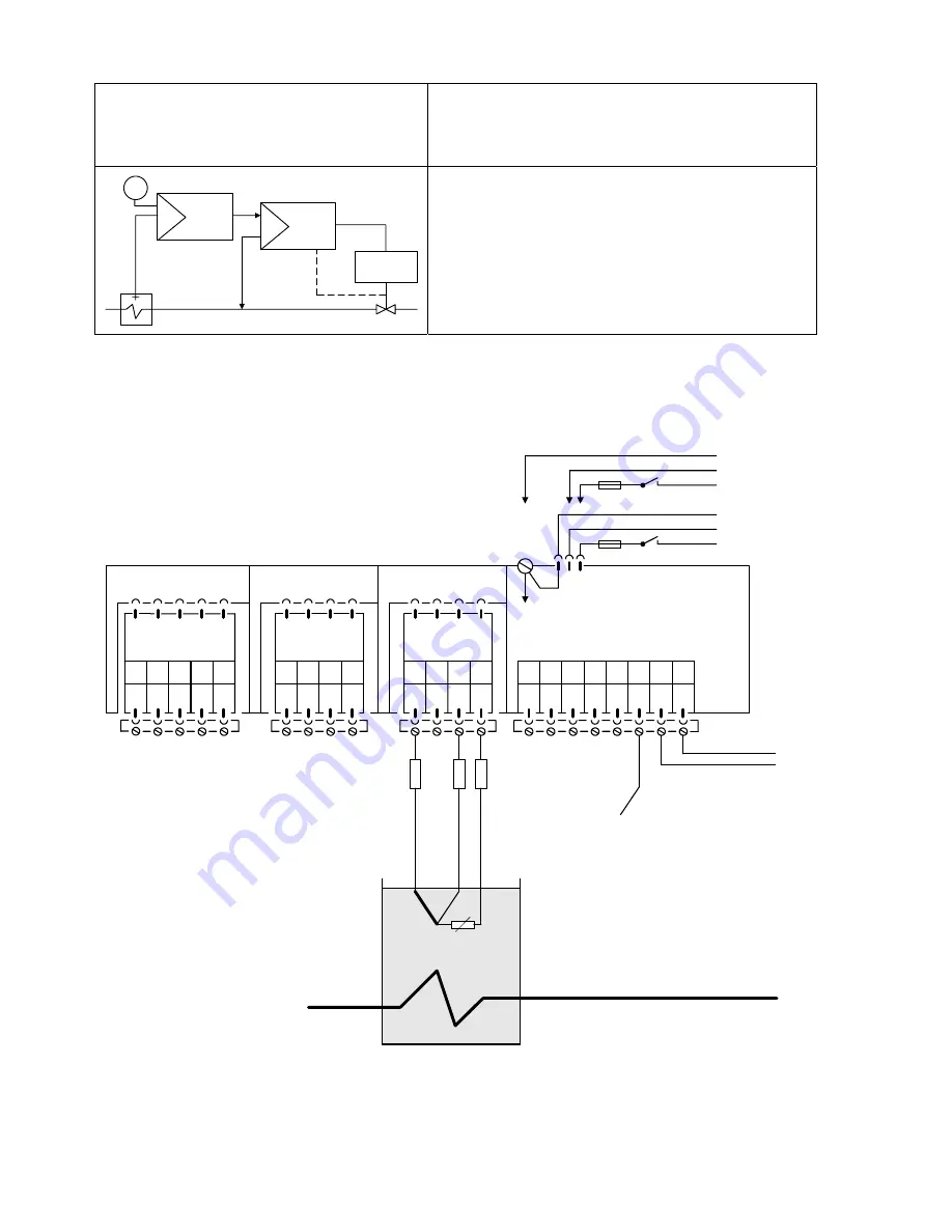
Planning example 

S6 


Cascade control 
Process variables for both controllers from 
resistance thermometers Pt 100


W

y

Drive

Y

R

Master

Slave

 
The master controller has a continuous output, the 
slave controller is a three-position step controller. 
The resistance thermometers are directly connected 
to the analog inputs AE3 of both controllers. 
The output signal of the master controller is the 
remote setpoint of the slave controller and linked to 
its analog input AE2. 


Please refer to the remarks on page 108 and the note on page 15 ! 
 
Setting of configuring switches: S8 = 1 
 

AE1

AE2

BE

BA

L+

GND GND

Iy

1

2

3

4

5

6

7

8

SIPART DR20 K

6DR2004-1 (AC 230 V)
6DR2004-2 (AC 115 V)
6DR2004-4

(UC 24  V)

1

2

3

4

1

2

3

4

1

2

3

4

PE

N

L

AC 115 V
AC 230 V

PE

N

UC 24 V

L

Slot 3    GW

Slot 2      AE4

Slot 1    AE3

5

M1

A1

R1

A2

M2

not equipped

M

M/A

S

E

Option module

6DR2800-8P

R

L1

R

L3

R

L4

Pt100

Master controller

not equipped

R

L1 

= R

L3

 = R

L4


 50 


130

Summary of Contents for SIPART DR20

Page 1: ...s Compact Controller SIPART DR20 Project Planning Manual 02 05 Order No 6ZB5600 0AAO2 0BA0 ...

Page 2: ...Project Planning Manual SIPART DR20 empty page 2 ...

Page 3: ... these are especially identified Notice The controller SIPART DR20 is powered by electricity Certain components within electrical instruments are by necessity subject to very high voltages Serious physical injury or damage to property equipment may ensue if the hints in this manual are ignored Only suitable qualified personnel should use this controller The trouble free and safe operation depends ...

Page 4: ...rt Conditions 58 3 2 6 Optical Signalling of Functions and Operating State 58 3 2 7 Bus Interface 60 4 Technical Data 62 5 Mounting 70 5 1 Mechanical Installation 70 5 2 Electric Connection 70 5 2 1 Wiring 71 5 2 2 Serial Interface and Bus Driver 71 6 Adjustments and Operation 87 6 1 Process Operation 87 6 2 Parameterization 88 6 3 Configuring 89 6 4 Lamp Test 91 6 5 Display of Software Version 91...

Page 5: ...w Certain sensors such as resistance thermometers resistance transmitters and thermocouples can be directly connected to the controller Otherwise transmitters supplying an electric output variable must be connected between the sensor and the controller Our controllers are designed for transmitters with standardized signal outputs 0 to 10 V 0 to 20 mA or 4 to 20 mA 1 3 Final Control Elements and Ac...

Page 6: ...d Tv Vv Kp Vv xd y0 0 PI y t Kp xd Tn PID y t Kp xd Tn Tv Vv 1 4 Controllers In the input circuit the controlled variable x is compared with the command variable W and the negative deviation xd is determined This is processed with or without a time response into the output signal The output signal of the amplifier can represent the manipulated variable w directly e g if it controls final control e...

Page 7: ...the derivative action gain Vv and the derivative action time Tv The controller output signals must be matched to the actuators Two types of controllers are common for the most important kinds of actuator Æ three position step controllers for electric actuators and Æ continuous controllers for pneumatic and hydraulic actuators The three position step controller switches the electric motor of the ac...

Page 8: ...lication of continuous controllers is in installations with pneumatic actuators The controller output signal of 0 to 20 mA or 4 to 20 mA acts continuously on the final control element through an electropneumatic signal converter w 3 2 x xd 4 1 y 0 2 1 0 bar y x 5 0 20 mA 4 20 mA w Command variable x Controlled variable xd Negative deviation 1 Transmitter 2 Setpoint adjuster 3 Control amplifier 4 E...

Page 9: ...ter 2 Control amplifier 3 Duty factor converter 4 Controlled system 5 Transmitter Fig 1 7 SIPART DR20 two position controller In the case of controllers with mechanical contacts the switching frequency possibly is limited because of the contact life However if thyristor units are used as switching elements the switching frequency can be increased The control problem often requires the controller a...

Page 10: ...vices from the TELEPERM D range The SIPART DR20 can be programmed to the most common types of controller Fixed setpoint controller with and without disturbance variable feedforward at input and output DDC backup fixed setpoint controller Follow up controller with and without local remote switchover SPC Synchronization controller for controlled variable Ratio controller In addition the device can a...

Page 11: ...ntrollers when y is switched through 7 2 Point lights up in S controllers when y is switched through 8 Selector for digital display 4 for activation of parameterization configuring and for lamp test 9 1 LED lights up if w is output in display 4 9 2 LED lights up if x is output in display 4 10 Selector for manual automatic mode 11 LED lights up in manual mode flashes with remote intervention N Si B...

Page 12: ... AE4 unfitted with dummy panel 3 Slot GW unfitted with dummy panel 4 Slot SES module pulled out 5 Terminal block of standard controller 6 Earthing screw 7 Mains plug 8 Clamp for fixing the device in a panel second clamp underneath device Fig 2 2 Rear view of SIPART DR20 12 ...

Page 13: ...r a floating condition is desired and the SIPART DR20 can also process three analog input signals simultaneously two of the rear slots are designed for fitting with additional input modules The arrangement of the fixed and optional input signal converters to the process signals is optional the possibilities are shown in Fig 3 1 AE3 I 0 4 20 mA 0 4 20 mA I I U R P T I U R P T Options AE4 AE2 2 AE1 ...

Page 14: ...dules or controllers The terminal blocks have different number of poles and mixing up in a controller is therefore impossible except AE3 and AE4 All additional modules are protected against incorrect insertion by mechanical coding of the circuit boards The slots are closed by covers if additional modules are not used 3 1 1 Front module The front module consists of a plastic frame material Macrolon...

Page 15: ...tons can therefore be activated simultaneously T activated on the front module which are required for the specific function Elements not require a particular function have no effect 3 T signals of the standard controller to the microcontroller of the front module This results in the following function units power pack for the AC DC 24 V design a highly efficient voltage stabilizer for the a short ...

Page 16: ...e wire or four wire system within a measuring range from 50 to 850 C Span 50 C the start of scale and span values can be set on the module using jumpers the fine adjustment of the start of scale and full scale values is made on the rear of the device during operation The output is linear 6DR2800 8T Input module for mV signals or for direct connection of thermocouples The span is 10 mV the start of...

Page 17: ... facilities via the front module of the device are blocked 3 1 3 3 Serial Interface SES 6DR2803 8A Interface module to connect the SIPART DR20 to a serial data bus The levels of this data bus are based on V 28 switching to V 28 point to point communication is possible using a jumper Using this module the device can transmit and receive process variables operating states parameter settings and conf...

Page 18: ... are made on the front of the SIPART DR20 without an additional programmer The problem specific program produced in this manner is stored in the non volatile part of the data memory and is therefore protected against power failure There are 48 configuring switches S1 to S48 A setting corresponding to the desired function can be selected for each switch from a function table The factory settings of...

Page 19: ...tion for I U R P T Analog inputs S9 0 1 Allocation of the analog inputs to the position feedback YR or position tracking YN AE 2 0 4 to 20 mA without electrical isolation AE 4 option for I U R P T Table 3 1 Configuring switches Structuring switches and positions Function S10 2 1 0 1 Allocation of the analog inputs to the auxiliary controlled variable X2 command variable X2 ratio control or remote ...

Page 20: ...ety manipulated variable Output switchover S31 0 1 2 Blocking of the manual automatic switchover No Only automatic operation switchover to manual mode not possible Only manual operation with interlocking the y readjustment facility can be switched off by key 10 LED 11 then does not light up S32 0 1 OFF Manipulated variable display Control output Y Feedback signal YR No display Y Display S33 0 1 Se...

Page 21: ...nual operation local with w ws or wv wvs y as S41 2 Without flashing of display 4 Structuring switches and positions Function S42 0 1 2 Serial interface only in conjunction with optional module 6DR2803 8A Without controller transmits all variables receives none With controller transmits all variables receives only parameters and structuring switches With controller transmits all variables receives...

Page 22: ... to AE3 and AE4 and with 0 to 10 V signals Signal assignment Up to three analog input variables can be processed for the control tasks of the device Main controlled variable x1 Remote setpoint wE command variable x2 with ratio controller disturbance variable x2 Position feedback yR position tracking yN The four analog inputs AE1 to AE4 are assigned to these variables using the configuring switches...

Page 23: ...nd example The linearization circuit must always be used in the case of non linear input values since intermediate values can only be indicated correctly on the digital display in this manner The control response is also improved Digital input BE The controller has a digital input which acts normally digital signal 13 V logical 1 or inverted digital signal 4 5 V or open circuit logical 0 according...

Page 24: ...l Unauthorized adjustments to parameters or configuring switches can then be prevented CB without acknowledgement 6 BL Blocking of manipulated variable function as Switch position 0 7 Si Safety manipulated variable function as Switch position 1 8 N Tracking of output function as Switch position 2 9 CB Computer enabled function as Switch position 3 10 SES The binary input only acts on the serial in...

Page 25: ...3 9 5 11 2 8 S15 S42 S42 S42 2 2 0 1 0 1 0 1 0 1 2 3 4 SES BL MuSt INT A2 A1 H yE CB Si N BE PS Fig 3 3 Digital functions via digital input output and the serial interface including status signals 3 2 2 Input Signal Processing and Switchover The following functions are explained in this section Manual setpoint input wi or setpoint ratio wv x tracking Setpoint limiting and setpoint ramp Formation o...

Page 26: ...matic mode in the function displays Thus when returning to automatic mode the control loop can be closed without bumps and drift with xd 0 The setpoint may have changed in the process Setpoint limit and setpoint ramp In all controller types the setpoint or the setpoint ratio can be limited by the parameters wa and we within the measuring range adjusted In the ratio controller and ratio station the...

Page 27: ...l point S21 the repetition rate of the displays With software version A06 A07 it is also possible to set the full scale value LE below the start of scaIe value LA i e to operate the controller with falling characteristic of the actual value The setpoint ratio actual ratio and limit setting are displayed with ratio controllers and ratio stations The decimal point is fixed at x xxx so that ratio fac...

Page 28: ...d the disturbance variable x2 r which can be apportioned using c2 are added to the main controlled variable x1 r 1 which can be processed further as the controlled variable x x x1 c1 c2 x2 The calculation is made between 0 and 100 The constants c1 and c2 can be set as parameters between 199 9 corresponds to number 1 999 and 199 9 corresponds to number 1 999 The effective controlled variable x is d...

Page 29: ...tion The evaluation and the addition of the disturbance variable to the output signal are described in Section 3 2 3 page 44 S1 3 DDC backup fixed setpoint controller Fig 3 6 In the case of direct digital control DDC all control functions are transferred directly from a process computer control system but individual loops or all loops are frequently protected by parallel hardware controllers Their...

Page 30: ...DDC mode RC CB I H with S29 1 see Fig 3 8 No status LED lights up on the controller in DDC mode The value which becomes effective upon computer failure is always indicated as the setpoint If the computer fails CB 1 Æ 0 the green LED of the Local display 14 flashes and the controller continues to operate with the displayed internal setpoint After switching over to local mode green LED 14 steady the...

Page 31: ... wi n wi n wi n Safety mode 0 0 1 0 1 1 0 1 1 1 yBL wi wi n wi n wi n Blocking mode 1 0 1 0 1 1 0 5 1 1 yBL wi wi n wi n wi n Blocking mode 0 1 1 0 1 1 0 1 1 1 yS wi wi n wi n wi n Safety mode 1 1 1 0 1 1 0 5 1 1 yS wi wi n wi n wi n Safety mode Computer switched off controller not at DDC backup standby 0 0 0 1 1 0 9 0 1 1 yA n wi wi n wi n wi n Automatic mode 1 0 0 1 1 0 9 1 1 1 yH n wi wi n wi n...

Page 32: ...n wi n wi n Safety mode 1 1 0 0 1 1 0 5 1 1 yS wi wi n wi n wi n Safety mode 0 0 1 0 1 1 0 1 1 1 yBL wi wi n wi n wi n Blocking mode 1 0 1 0 1 1 0 9 1 1 yH n wi wi n wi n wi n Manual mode 0 1 1 0 1 1 0 1 1 1 yS wi wi n wi n wi n Safety mode 1 1 1 0 1 1 0 1 1 1 yS wi wi n wi n wi n Safety mode Computer switched off controller not at DDC backup standby 0 0 0 1 1 0 9 0 1 1 yA n wi wi n wi n wi n Auto...

Page 33: ... push buttons on the front of the controller have no effect The local remote selector pushbutton 13 is also ineffective and the green LED 14 does not light up The device can be switched to manual mode as before or switched to one of the functions BL Si or N via the digital input and according to the position of the configuring switch S15 X1 wS WES SES S42 0 2 INT INT gn SP w wi w w X2 WEA 1 0 S18 ...

Page 34: ...ring switches S17 S18 and S19 Signals Control commands front and digital inputs Front LED Digital output Effec tive output Effective setpoint S19 0 H N Si BL CB INT INT H RB RC Y S17 0 S18 0 1 0 0 1 1 1 Explanations Computer failure 0 1 0 0 0 0 0 yA n wE n wE n wE n wE n Automatic mode SPC mode 0 0 0 0 5 0 0 1 yA n wi n wi n wS wS Automatic mode computer switched OFF controller at SPC standby 0 1 ...

Page 35: ... 1 1 yBL wi x wi x Manual tracking safety mode or blocking of output Fig 3 11 Follow up controller with local remote switchover without tracking of the local setpoint S19 1 operation with several setpoints When using the digital input BE only one of the control variables CB Si BL or N is possible as defined by S15 The priority is Si before BL before N DDC when applied via the serial interface The ...

Page 36: ...matic mode with setpoint 1 0 0 0 5 0 0 1 yA n wS wS Automatic mode with setpoint 2 1 1 1 0 1 1 yH yN wi x 1 0 0 5 0 1 1 yBL ySi wS x Manual tracking safety mode or blocking of output Fig 3 12 Follow up controller with local remote switchover Operation with two setpoints adjustable on front panel X1 wS WES SES S42 0 2 INT INT gn SP w wi w w X2 WEA 1 0 S18 wi CB CB INT INT wa we Tw 0 1 S19 1 wE X 0 ...

Page 37: ...d 0 2 1 S23 A2 A1 a1 a2 S17 A A 0 1 X S22 D element c1 c2 w c2 c1 wE SES Fig 3 14 Processing of command variable and formation of negative deviation in synchronization controller S1 7 Ratio controller Fig 3 15 In a ratio controller the command process variable x2 is weighted by the ratio factor v and forms the setpoint for the controlled process variable x1 w v x2 When xd w x then xd v x2 x 1 With...

Page 38: ...al display and used for x tracking if applicable The display range for ratio factors is 0 000 to 9 999 negative values are suppressed The negative deviation display indicates xd w x as with the other controller types The setpoint ramp Tw is only effective at OFF or from 1 to 100 s The alarm function enables monitoring of the actual ratio or the setpoint ratio x1 INT INT gn SP w wvi w w x2 wva wve ...

Page 39: ...atio controller except that the processed command variable w is processed further directly as the output signal yA yA w v x2 c1 This signal is indicated in the two digit display in percent The four digit display indicates as with the ratio controller the ratio factor wv which can be adjusted using the setpoint pushbuttons with selector 8 in position SP w As with the ratio controller the range of a...

Page 40: ...ion DDC manual control station Fig 3 18 Manual control station S31 2 In this type of circuit the device outputs a signal which can be adjusted using the manipulated variable pushbuttons It is output directly in percent in the two digit display in a standard K controller and a standard S controller with three position step output if the position signal is fed back to the device via the input yR Man...

Page 41: ...racking and wS following computer failure must be switched off S17 0 S18 0 X1 INT INT gn SP w wi w w wa we Tw 0 0 0 0 S20 S21 Display Key 8 8 8 8 8 8 8 4 SES W X 0 2 1 S23 A2 A1 a1 a2 Key Key 8 8 8 8 8 8 8 13 S22 Fig 3 18 Manual automatic control station DDC manual control station DDC manual control station x and w display and alarm monitor See Section 3 2 4 for diagrams of output circuit page 46 ...

Page 42: ...20 mA via the analogue output It is a setpoint transmitter with local remote switchover in addition If the basic device is an S controller the signals of a second alarm monitor can be output via the Y outputs The switching thresholds of this alarm monitor are set by parameters ya min and ye max with a hysteresis of 1 The associated input signal is yR yN X1 wS WES SES S42 0 2 INT INT gn SP w wi w w...

Page 43: ...splayed referred to the measuring range The display range can be modified using configuring switch S25 between 2 5 and 40 negative deviation The 21 LEDs are divided as follows 10 red LEDs to display a positive deviation i e the setpoint is larger than the actual value In the factory setting the 1st LED lights up with xd 0 5 the 2nd LED above xd 1 5 up to the 10th LED above 9 5 The result is a red ...

Page 44: ...0 3 1 2 ig 3 20 PID controller structure Response threshold for xd dead zone element If the controller output is to be dampened in addition to the effect of the filter it is possible to set a response threshold for the negative deviation parameter A See adjacent Fig 3 21 It is essential to set A 0 in the case of S controllers two position controllers with 2 outputs and three position step controll...

Page 45: ... D control algorithms are implemented in the same manner independent of the output configuration S or K Configuring switch S28 is used to select P or PI control As can be seen in Fig 3 20 the algorithm has a parallel configuration with interaction free parameter setting The following controller equations apply to a normal action system if the cycle time filter time constant tF and response thresho...

Page 46: ...and ye have a different meaning in this case see Section 3 2 4 Manipulated variable limitation is not possible with three position step controllers with internal simulation of the position S2 2 3 2 4 Output Signal Processing and Switchover The following functions are described in this section Possible operating modes Priority switchover of manual and tracking mode blocking Manual manipulated varia...

Page 47: ...ith a two position output Three position step controllers with external position feedback the tracking signal can be tracked via the serial interface yES No tracking of the manipulated variable is possible in three position step controllers with internal position feedback H Manual operation y yH The manipulated variable is adjusted using the two keys 5 1 and 5 2 Only one control signal can be defi...

Page 48: ... in three position step controllers are simulated by manipulated variable signals 0 and 100 so that they act on the outputs y and y like direct positioning commands continuous contact All switchover functions and the minimum pulse lengths te and pulse pauses ta remain effective however Position feedback yR A feedback via input yR must be made in three position step controllers to display the posit...

Page 49: ...al even if this has only been prepared and is not yet effective because of a priority e g BI or N S34 2 RB Controller not in computer readiness lNT or H S34 3 Must Transmitter fault collective signal This fault signal is only output if S11 is programmed accordingly Fig 3 2 S34 4 SES The digital signal is activated via the serial interface only Special functions of the alarm output module Configuri...

Page 50: ...eration Signals Control commands front and digital inputs Front LED Digital output Effective output Explanations Si H BL N H H Y 0 0 0 0 0 0 yA Automatic mode 0 0 0 1 0 1 0 yN Tracking mode 0 0 1 1 0 1 0 yBL Blocking mode 0 0 1 1 0 1 0 yBL Blocking mode 0 1 0 0 1 1 yH Manual mode 0 1 0 0 0 9 1 yH Manual mode 0 1 1 1 0 9 1 yH Manual mode 0 1 1 1 0 9 1 yH Manual mode 1 0 x x 0 1 0 yS Safety mode 1 1...

Page 51: ...S1 3 and 9 S2 0 This facility is required if more than one manipulated variable output e g from the controller and a computer is to act on an actuator and only one output may apply a current Feedback into the controller output stage is prevented by the diode in the current output The output stage of the computer connected in parallel must then also be equipped with a blocking diode The complete K ...

Page 52: ... switch off durations and is defined as Switch on duration Control Ratio Switch on duration Switch off duration The switch on and switch off durations together result in the period This can be adjusted in the SIPART DR20 The range of y from 0 to 100 can be divided into two sections A parametrizable dead zone ye ya is present between these two sections Fig 3 27a and note on page 53 The slope of the...

Page 53: ... output y should be used and ya and ye both set to 100 ON ON switch on duration switch off duration OFF Output y Output y Period T Period T switch on duration switch off duration t Parameter T Ty Fig 3 26 Switch on duration switch off duration period The period T and T is adjustable The switch on and switch off durations are then longer or shorter accordingly The ratio between these two is not cha...

Page 54: ...0 2 1 3 4 RB RC SES MuSt H 0 1 BA S35 y yA yR yN yH yS H H S31 0 2 1 y N DDC Si S32 0 1 ya T y y y S33 S21 0 0 DDC RC INT CB yE 1 0 with S1 9 yES SES S42 0 1 2 Bl TY SES Fig 3 28 Output configuration of two position controller manual mode has priority over tracking mode blocking S34 0 2 1 3 4 RB RC SES MuSt H 0 1 BA S35 y yA yR yN yH yS H H S31 0 2 1 y N DDC Si S32 0 1 ya T y y y S33 S21 0 0 DDC R...

Page 55: ...iable with this output configuration Therefore limitation of the manipulated variable using parameters ya and ye a parametrizable safety setting yS and a pure P control are not possible The position controller has a minimum pulse length te adjustable using configuring switch S39 and a minimum pulse pause ta adjustable using S40 The minimum pulse length te results in a response threshold as follows...

Page 56: ...iable is possible using parameters ya and ye and an absolute value can be entered for the safety manipulated variable yS DDC or tracking mode via yES is also possible with S42 2 P controls are also possible Caution Since the external feedback circuit must never be interrupted it is highly recommendable to provide the final control element with an electronic position transmitter and to feed the fee...

Page 57: ... position step controller with external position feedback tracking mode blocking has priority over manual mode S34 0 2 1 3 4 RB RC SES MuSt H 0 1 BA S35 y yA yR yN SES yH yS yES H S42 H N DDC S31 0 2 1 y Bl Si S32 0 1 tA tE SES S39 S40 y y y S33 S21 0 0 DDC RC INT CB 2 Fig 3 33 Output configuration of three position step controller with external position feedback manual mode has priority over trac...

Page 58: ...lated variable is not retained The possibilities for S41 listed in the configuring table are self explanatory 3 2 6 Optical Signalling of Functions and Operating States Various functions and operating states can be activated either by manual interventions on the control keyboard or via a digital function depending on the various configuring switch settings as described in the previous sections Opt...

Page 59: ...o the effective setpoint w wS wE x tracking S17 1 not with local operation mode wS S18 1 effective with INT AND CB Æ not with S1 10 adjustable Cofiguring switch Æ S1 0 1 2 4 5 6 7 8 10 S1 3 9 Selected function H A automatic mode H manual mode H A automatic mode H manual mode yA yH N Si BL 0 yE yE S29 0 Si BL 0 yBL yN yBL yN S29 0 BL N 1 yE yH S29 1 Si BL 0 DDC backup mode yBL yN yH S29 1 BL N 1 yA...

Page 60: ...A or B commences with the start character STX followed by the station number the data the end character ETX and if applicable a cross check sum for additional data protection The quantity of data to be transmitted the start address of a list range and a code for transmitting or receiving data are first defined in the data to be sent to a controller These are then followed if applicable by the data...

Page 61: ...ages do not follow within the set monitoring time and the CBes signal is set to zero The associated controller then enters stand alone mode The interface operating instructions C73000 B7476 128 are available for producing coupling software to higher level systems Example Setpoint W READ and WRITE Default settings S1 5 S42 2 S43 46 0 S47 StNr 0 S48 0 Process values are LIN values 100 LIN 8000 Hex 3...

Page 62: ...ctive screen or increased insulation to DIN VDE 106 Part 101 Nov 86 IEC 536 The outputs are small function voltages to DIN VDE 0100 Part 410 Nov 83 IEC 364 4 41 Clearances and creepage paths if not specifically stated otherwise for over voltage class III and contamination class 2 to DIN VDE 0109 Dec 83 IEC 664 and IEC 664A Isolation between y contacts of the S controller and the field signals by m...

Page 63: ...ces Cut out width b 2 3 4 10 140 1 212 1 284 1 716 1 1 Mounting depth required to replace the signal converters 2 But mounting above each other is permissible within the permissible ambient temperature range Fig 4 1 Dimensions Fig 4 2 Panel cut outs 63 ...

Page 64: ...Hz 78 V 500 V 30 ms 21 VA inductive 13W AC 500 V DC 700 V DC 700 V DC 20 to 35 V 78 V 500 V 30 ms 13W AC 500 V DC 700 V DC 700 V The transmitter supply can fall by up to 5 V the max load voltage of the manipulated variable current Iy from 18 to 13 V Transmitter supply L Rated voltage Residual ripple 100 120 Hz Upp Max permissible load current Short circuit current 20 to 26 V 1 V 60 mA short circui...

Page 65: ...tatic destruction limit Dynamic destruction limit 0 to 20 mA or 4 to 20 mA 0 to 22 mA or 2 4 to 22 mA 1 to 18 V 26 V 0 1 0 1 H 0 1 0 1 0 2 0 3 0 1 10 K 0 3 10 K 0 2 330 ms 1 V 35 V 500 V 1 2 50 µS Ri 13 Ω Relay outputs Y S controller Contact material Ag Ni Alternating current Direct current Contact loading capacity Max switching voltage Max switching current Max switching power AC 250V 5A 1250 VA ...

Page 66: ...ngth of display Display range Resolution Resolution around xd 0 Repetition rate y display Color digit height Display range Repetition rate Resolution Display error four digit 7 segment display red 7 mm 1999 to 9999 adjustable can be fixed 0 1 to 5 s adjustable together with y display 1 digit but not better than A D converter corresponding to A D converter and analog inputs 20 red LEDs 1 green LED ...

Page 67: ...kΩ 0 to 10 V 200 kΩ 200 kΩ 0 to 10 V 5 mA 5 10 Ω each 100 mV R RL1 RL2 10 Ω RL1 RL2 RL3 50 Ω RL 80 Ω 2 MΩ 1 MΩ 10 to 10 V RL1 RL2 300 Ω Filter time Constant 20 50 ms 50 ms 50 ms 50 ms 20 ms Error Zero Gain Linearity Common mode Cold junction compensation 0 3 0 5 0 05 0 07 V 0 2 0 2 0 05 0 02 V 0 2 0 2 0 2 0 1 0 1 0 3 0 1 0 1 0 1 0 1 V 2 C Influencing effect of temperature Zero Gain Cold junction c...

Page 68: ... varistor 75 Vrsm Alarm module with 4 digital outputs and 1 digital input 6DR2801 8B Outputs Signal status 0 Signal status 1 Max load current Short circuit current Static destruction limit Dynamic destruction limit Input Signal status 0 Signal status 1 Input resistance Static destruction limit Dynamic destruction limit 4 digital outputs of which 2 for alarm monitoring 2 for the outputs with an S c...

Page 69: ...racter with 7 bit parity bit and stop bit 2 or 4 300 to 9600 bit s Asynchronous half duplex Full duplex for NAK 32 1 to 25 s or none V 28 UA 5 to 12 V IA max 1 67 mA short circuit IA max 15 mA proof UA 5 to 12 V IA max 1 67 mA UA 0 V V 28 UA 0 to 35 V IE UE 0 7 V 6 8 kΩ UA 3 to 35 V IE UE 1 5 V 6 8 kΩ Txd without referred to M Ground Rxd by opto isolator Recommended length Cable capacitance and le...

Page 70: ...lamp range is from 0 to 40 mm 5 2 Electric Connection Caution The regulations for the installation of power systems with rated voltages below 1000 V must be observed VDE 0100 A protective earth connection has to be made and must not be disconnected while the controller is powered The arrangement of the connection elements is shown in Fig 2 2 page 12 Protective earth connection The protective earth...

Page 71: ...essary The 10 way and 8 way terminal blocks are supplied with the driver 9 way D plug for round cable soldered C73451 A347 D35 9 way D plug for ribbon cable i p c d C73451 A347 D36 25 way D plug for round cable soldered C73451 A347 D38 Recommended cables FLi Y10 x 1 x 0 14 mm 10 core ribbon cable AWG 26 JE LiYY 4 x 1 x 0 5 BdSi core unscreened round cable Zero volt system The SIPART DR20 controlle...

Page 72: ... or AE2 Connection with a non floating current source 249 Ω I 0 4 to 20 mA AE 1 AE 2 1 2 6 M UH 249 Ω I 0 4 to 20 mA AE 1 AE 2 M 1 2 5 L 6 Connection circuit of AE1 or AE2 Connection of a two wire transmitter to AE1 or with a floating current source AE2 with power from L of controller Fig 5 2 Wiring of analog inputs AE1 and AE2 72 ...

Page 73: ...the transmitter The module is set to process current signals by means of jumpers on the module itself and an appropriate connection The measuring range 0 to 20 mA or 4 to 20 mA is set by configuring Connection examples for current signals are shown in Fig 5 4 The voltage input is also connected across the input terminals AE and AE As with the connection to current signals the common mode suppressi...

Page 74: ...to 20 or 4 to 20 mA 3 1 2 4 6DR2800 8J 49 9 Ω AE3 AE4 6 M Standard controller AE AE 3 1 2 4 6DR2800 8J 49 9 Ω AE3 AE4 6 M Standard controller AE AE Ι 0 4 to 20 mA Device 1 Device 2 1 The common mode voltage may be up to 10V A total resistance against the reference potential is therefore permissable up to 500Ω at this position Note the minimum operating voltage of the two wire transmitter Series co...

Page 75: ...n error 3 1 2 4 6DR2800 8J 49 9 Ω U AE3 AE4 6 M Standard controller AE AE 0 to 10 V Connection circuit of signal converter 6DR2800 8J as voltage input for a non floating voltage source of 0 to 10 V whilst avoiding voltage drops on the M bar 3 1 2 4 6DR2800 8J 49 9 Ω U AE3 AE4 6 M Standard controller 0 to 10 V AE AE Connection circuit of signal converter 6DR2800 8J as voltage input for a floating v...

Page 76: ...ax 20 mA 1 kΩ 500 Ω 200 Ω 2 4 RA R RE UH Fig 5 6 Wiring of module 6DR2800 8R for current signals resistance transmitter Pt 100 resistance thermometers can be connected using a two wire three wire or four wire system The selection is made using jumpers on the module The following conditions apply 6DR2800 8P see wiring diagram Fig 5 7 Two wire circuit RL1 RL4 10 Ω Three wire circuit RL1 RL3 RL4 50 Ω...

Page 77: ...4 289 5 288 4 291 5 290 4 293 5 294 4 297 6 296 4 299 6 298 4 301 6 300 4 303 6 301 4 304 5 303 4 306 5 305 4 308 5 307 4 310 5 309 4 312 6 311 4 314 6 313 4 316 6 315 4 318 6 G GH GH GH GH GH G G GH GH GH GH G GH G GH GH GH GH G G G GH GH GH G GH GH G GH GH GH G GH G G GH GH GH G G GH G GH GH GH G G G G GH GH G GH GH GH G GH GH G GH GH G G GH GH G GH G GH G GH GH G GH G G G GH GH G G GH GH G GH G...

Page 78: ...0 controllers are provided with a thermocouple input and connected together via the ground lead If this is not the case it is recommendable to connect terminal 3 to M terminal 6 of standard controller Electrical isolation is then provided via the mains transformer Fine adjustment with a mV transmitter must also be carried out with this connection Thermocouples can be connected either via thermosta...

Page 79: ...e rear For operation set jumper to NORM position for thermocouples using the internal cold junction Leave it on TEST for thermocouples using external compensation or mV transmitters 9 7 10 3 10 1 10 7 10 6 11 2 11 0 11 7 11 5 12 0 13 2 13 9 13 8 14 6 14 4 15 0 14 9 15 7 15 5 16 4 16 7 17 3 17 1 18 1 18 0 19 2 18 9 20 0 19 6 20 6 20 3 21 3 21 2 22 5 22 0 23 2 23 0 24 2 23 9 24 9 24 5 26 0 25 8 27 5...

Page 80: ...he relay contacts 6DR2801 8B see connection diagram Fig 5 10 If this module is fitted for alarm monitoring configuring switch S36 must be set to 1 The external signalling of alarms is then made via the digital outputs A1 A2 With an S controller the manipulated variable signal is also output at the same time via this module Y and the output relays in the standard controller are switched off This mo...

Page 81: ...ll as digital input BLPS 5 2 2 Wiring the Serial Interface and the SIPART Bus Driver 6DR2803 8A V 28 point to point serial interface Insert in slot 4 Use configuring switches S42 to S48 to establish communications procedure V 28 50 m 6K81 10 V 1 10 V 1 6DR2803 8A 1 x1 x2 x3 point to point Bus M 4 2 4 7 4 8 4 3 24 V 10 V 10 V 10 V 24 V M 5 V 5 V 10 V TxD RxD Remote system Common Fig 5 11 Wiring of ...

Page 82: ...Project Planning Manual SIPART DR20 SIPART Bus Fig 5 12 SES bus driver remote system wiring diagram 82 ...

Page 83: ...SIPART DR20 Project Planning Manual SIPART bus wiring principles Fig 5 13 Wiring of SES bus driver to SIPART bus 1 marshalling SES on bus x1 x2 83 ...

Page 84: ...2 wiring principles and interface to remote system Fig 5 14 V 28 point to point to a remote system with no isolation between the SIPART bus and the remote system Fig 5 15 V 28 point to point to a remote system with the SIPART bus and the remote system isolated 84 ...

Page 85: ...IPART bus and remote system isolated Txd on the remote system is an active current source that is not isolated from Rxd Fig 5 17 TTY to remote system with the SIPART bus and the remote system isolated Txd on the remote system is an active current source isolated from Rxd 85 ...

Page 86: ...Project Planning Manual SIPART DR20 Fig 5 18 TTY to remote system with the SIPART bus and the remote system isolated Txd on the remote system is a passive switch Txd and Rxd are isolated 86 ...

Page 87: ...ondition on delivery inscription for scale range 10 The rear is not printed and can be inscribed with any scale ranges The vacant area can be used for further information e g TAG number measuring range dimension etc The LEDs 3 signal downward or upward violation of alarms A1 and A2 The four digit 7 segment display 4 outputs either the setpoint w green LED 9 1 lights up the actual value x red LED 9...

Page 88: ...ut wE or the communication input SES With ratio controllers and ratio stations With follow up SPC controllers With DDC backup controllers and DDC manual control stations Key 13 has no function in the case of follow up controllers without local remote switchover and in the case of synchronization controllers and manual automatic control stations LED 14 then remains dark Caution The following Sectio...

Page 89: ...on page 19 To select and set the configuration proceed in an analog manner to parameterization 1 Press selector 8 until the two digit display 6 outputs PS flashing Release push button the display PS becomes steady 2 Now press pushbutton 12 1 until the four digit display first indicates the letters PAr and then Str The controller can now be configured The controller now blocks its output Display 1 ...

Page 90: ...x 4 8 50 L4 L4 1999 9999 0 0 Vertex 5 8 62 5 L5 L5 1999 9999 0 0 Vertex 6 8 75 L6 L6 1999 9999 0 0 Vertex 7 8 87 5 L7 L7 1999 9999 0 0 See page 91 The parameters L1 to L7 are only required for a display of engineering units with linearization S14 1 Full scale value 100 1999 100 0 LE LE 9999 Set limitation Start wa 9999 SA 1999 5 0 Set limitation End we SE 1999 9999 105 0 Only values wa wva we wve ...

Page 91: ...when acknowledged by key 8 the basic setting w is retained This signal should be observed If parameterization or configuring was carried out immediately before it must be checked whether the new settings have already been transferred to the fail safe EEPROM page 88 The controller can also start up with preset safety values depending on the configuration selected using S41 Setting of linearizer a n...

Page 92: ...le 6 1 also shows the factory setting of the parameters It should be noted that some parameters ty SA SE A1 A2 yA yE determine values of different functions depending on the configuration of the device The compatibility of the factory settings with the selected operating mode should always be checked see also page 54 for example The output of the process variables in the four digit display can als...

Page 93: ... of thermocouples to DIN 43710 and DIN IEC 584 must always be observed Settings for standard measuring ranges for thermocouples have been prepared in the following Tables 6 3 and 6 4 Marshalling Parametrization U0 U Linearization Measuring range Type Pol Value 1 2 3 4 5 LA L1 L2 L3 L4 L5 L6 L7 LE wa we NiCr Ni K 0 600 C P 0 AB BC AB BC A 0 76 153 230 306 380 454 527 600 0 600 0 900 C P 0 AB AB BC ...

Page 94: ... A AB AB 300 338 376 414 452 491 527 564 600 300 600 Fe CuNi L 0 250 C P 0 AB A BC AB AB 0 33 65 96 128 158 189 220 250 0 250 0 400 C P 0 AB AB BC BC A 0 49 103 153 202 252 301 351 400 0 400 0 600 C P 0 A AB BC BC BC 0 79 155 230 305 380 455 528 600 0 600 300 600 C P 0 5 16 A A A BC AB 300 338 377 415 452 490 527 564 600 300 600 PtRh10 Pt S 0 1200 C P 0 A AB AB BC A 0 206 371 525 671 811 945 861 9...

Page 95: ... to the table 0 with a normal action system 1 with a reversed action system If the directions of action of the system and the final control element are not known set the controller to manual mode with S26 1 press the right hand manipulated variable pushbutton 5 2 briefly with the process switched off or in a safety position and observe whether the controlled variable x rises or falls A rising x me...

Page 96: ...itch S39 should be selected at least so large that the actuator is positively set into operation taking into account the series connected circuit breaker The larger the value of te the smoother and more resistant to wear are the switching elements and actuators The dead band is also larger however in which the controller cannot control in a defined manner since the resolution of the controlled var...

Page 97: ... response The parameters for optimum control of the system are not yet known The following factory settings have been made in order to achieve stable control nevertheless Proportional gain Kp 0 100 Reset time Tn 9984 s Derivative action time Tv OFF Three position step controller with external feedback S2 3 First optimize the position control loop in manual mode using ta and te If there are non lin...

Page 98: ...to zero in manual mode Switch to automatic mode Slowly increase Kp until the control loop tends to oscillate upon changes in the setpoint Slightly decrease Kp until the tendency to oscillate is eliminated Decrease Tn until the control loop tends to oscillate again Slightly increase Tn until the tendency to oscillate is eliminated PID controller S28 0 Adjust the desired setpoint and control the neg...

Page 99: ...ponse with Controlled Variable Subject to High Interference Set configuring switch S3 to the mains frequency 50 or 60 Hz of the power supply in order to largely suppress interferences from the mains frequency The factory setting is 50 Hz 1st order filter for negative deviation parameter tF the filter is switched on by the jump in the display from OFF to 1 s and can be matched to a low frequency in...

Page 100: ...ronic position transmitter Front command Manual mode wa we wE wES wi wS w Start of scale value Setpoint limitation or Full scale value ratio factor setting range Remote setpoint Remote setpoint via serial interface Local setpoint Safety setpoint Effective setpoint Int Iy Front command Local setpoint Current output manipulated variable x xd Effective actual value controlled variable Negative deviat...

Page 101: ... 8J 6DR2800 8R 6DR2800 8P 6DR2800 8T Relay output module For alarm signals 6DR2801 8A Digital output module For alarm signals and manipulated variable output of S controller 6DR2801 8B Serial interface module For serial communication RS 232 6DR2803 8A Mains plug for 115 230 V C73334 Z343 C3 Mains plug for 24 V C73334 Z343 C6 Terminal block 8 way for standard K controller W73078 B4 A908 Terminal bl...

Page 102: ...ment Setpoints states parameters and structure switches of the controllers can then be stored on floppy disks and reloaded from them 2 The Siemens digital compact controllers are highly suitable for use in higher level automation systems both in SPC and DDC backup modes For example a software package SIPART SW S5 is available for communication between the compact controllers and the SIMATIC S5 115...

Page 103: ...ld be set to 0 unless the controlled system requires a different setting Example 1 Fixed setpoint controller without setpoint ramp Tw 0 Operation with an adjustable setpoint wi no x tracking S1 0 S17 0 100 0 t w w1 wi adjustable on front Fig 11 1 Setpoint response according to example 1 Example 2 Fixed setpoint controller with setpoint ramp Tw 0 Operation with an adjustable setpoint wi with x trac...

Page 104: ...l remote switchover 1 One variable setpoint w1 c2 wE c1 2 The setpoint w2 c1 defined by parameterization and not affected by the front controls Both setpoints are thus linked by the fixed component c1 the switch over from w1 to w2 takes place simply by external switching off of w2 A setpoint ramp Tw 0 is provided S1 6 100 0 w1 w2 wE 0 t w w1 wE c2 c1 w2 c1 parameter wE Tw Fig 11 3 Setpoint respons...

Page 105: ...ng to example 4 S19 0 Example 5 Two setpoint mode as already described in example 4 but in this case the local setpoint wi is made to track the effective setpoint w The following function is then achieved if a switch is made to local using pushbutton 13 whilst the setpoint increases the last value is retained as wi until switched back to remote again If necessary wi can be changed on the front pan...

Page 106: ...tching between w1 w2 on the one hand and the setpoint w3 is carried out using the local remote pushbutton 13 Fig 11 6 shows the setpoint response with a setpoint ramp Tw 0 Fig 11 7 shows the same example without a setpoint ramp Tw 0 S1 5 S10 1 S15 3 S17 0 S18 1 S19 1 100 0 w1 w2 w3 w1 INT INT INT INT CB CB t w w1 wE w2 wS parameter w3 wi adjustable on front wE CB CB Fig 11 6 Setpoint response acco...

Page 107: ...setpoint we which is fixed by parameterization and cannot be influenced from the front panel The switchover is carried out by pushbutton 13 and the CB signal as follows w1 pushbutton 13 to local w2 pushbutton 13 to remote CB signal activated by L input AE3 applied to ground w3 pushbutton 13 to remote no CB signal w4 pushbutton 13 to remote CB signal activated by L input AE3 applied to L Limitation...

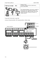
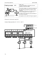
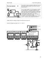
Page 108: ...power supply range and controller type are defined Alarm signalling A module for external signalling of alarms is included in all examples This module can be omitted if external signalling is not required A connection circuit for the alarm module is not shown since this differs from case to case The relay module must only be connected to low voltages see page 68 Input circuits All possible input c...

Page 109: ... using configuring switch S28 1 If this is necessary it is essential to connect an electronic position transmitter EPT via yR in the case of a SIPART DR20 with S output and to set configuring switch S2 3 List of planning examples Page K1 Fixed setpoint controller controlled variable from four wire transmitter 112 K2 Fixed setpoint controller controlled variable from two wire transmitter 113 K3 Fix...

Page 110: ...l cold junction position feedback from electronic position transmitter EPT 128 S5 Fixed setpoint controller with disturbance variable feed forward at input controlled variable direct from Pt 100 disturbance variable from transmitter position feedback from potentiometer 129 S6 Cascade control with a continuous controller as master and a three position step controller as slave controller 130 S7 Rati...

Page 111: ...SIPART DR20 Project Planning Manual Empty page 111 ...

Page 112: ...om the controller to terminal 5 1 to terminaI 6 The alarm circuit monitors the negative deviation xd for max min deviations set parameters A2 and A1 PIease refer to the remarks on page 108 Setting of configuring switches All configuring switches in factory setting AE1 AE2 BE BA L GND GND Iy 1 2 3 4 5 6 7 8 SIPART DR20 K 6DR2004 1 AC 230 V 6DR2004 2 AC 115 V 6DR2004 4 UC 24 V 1 2 3 4 1 2 3 4 1 2 3 ...

Page 113: ...4 to 20 mA The alarm circuit monitors the negative deviation xd for max min deviations set parameters A2 and A1 PIease refer to the remarks on page 108 Setting of configuring switches S4 1 S37 1 AE1 AE2 BE BA L GND GND Iy 1 2 3 4 5 6 7 8 SIPART DR20 K 6DR2004 1 AC 230 V 6DR2004 2 AC 115 V 6DR2004 4 UC 24 V 1 2 3 4 1 2 3 4 1 2 3 4 PE N L AC 115 V AC 230 V PE N UC 24 V L Slot 3 GW Slot 2 AE4 Slot 1 ...

Page 114: ...output is 0 to 20 mA a signal range of 4 to 20 mA can be set using configuring switch S37 1 The alarm circuit monitors the controlled variable temperature set parameters A2 min and A1 max PIease refer to the remarks on page 108 Setting of configuring switches S8 1 S22 1 AE1 AE2 BE BA L GND GND Iy 1 2 3 4 5 6 7 8 SIPART DR20 K 6DR2004 1 AC 230 V 6DR2004 2 AC 115 V 6DR2004 4 UC 24 V 1 2 3 4 1 2 3 4 ...

Page 115: ...ut is 0 to 20 mA a signal range of 4 to 20 mA can be set using configuring switch S37 1 The alarm circuit monitors the controlled variable temperature set parameters A2 min and A1 max PIease refer to the remarks on page 108 Setting of configuring switches S8 1 S22 1 AE1 AE2 BE BA L GND GND Iy 1 2 3 4 5 6 7 8 SIPART DR20 K 6DR2004 1 AC 230 V 6DR2004 2 AC 115 V 6DR2004 4 UC 24 V 1 2 3 4 1 2 3 4 1 2 ...

Page 116: ...le output is 0 to 20 mA a signal range of 4 to 20 mA can be set using configuring switch S37 1 The alarm circuit monitors the controlled variable temperature set parameters A2 min and A1 max PIease refer to the remarks on page 108 Setting of configuring switches S8 1 S22 1 AE1 AE2 BE BA L GND GND Iy 1 2 3 4 5 6 7 8 SIPART DR20 K 6DR2004 1 AC 230 V 6DR2004 2 AC 115 V 6DR2004 4 UC 24 V 1 2 3 4 1 2 3...

Page 117: ... variable output is 0 to 20 mA it can be reconfigured to 4 to 20 mA S37 1 The alarm circuit monitors the negative deviation Xd for max min deviations set parameters A2 min and A1 max PIease refer to the remarks on page 108 Setting of configuring switches S8 1 S14 1 AE1 AE2 BE BA L GND GND Iy 1 2 3 4 5 6 7 8 SIPART DR20 K 6DR2004 1 AC 230 V 6DR2004 2 AC 115 V 6DR2004 4 UC 24 V 1 2 3 4 1 2 3 4 1 2 3...

Page 118: ...utput is 0 to 20 mA it can be reconfigured to 4 to 20 mA S37 1 The alarm circuit monitors the negative deviation Xd for max min deviations set parameters A2 min and A1 max PIease refer to the remarks on page 108 Setting of configuring switches S8 1 S14 1 AE1 AE2 BE BA L GND GND Iy 1 2 3 4 5 6 7 8 SIPART DR20 K 6DR2004 1 AC 230 V 6DR2004 2 AC 115 V 6DR2004 4 UC 24 V 1 2 3 4 1 2 3 4 1 2 3 4 PE N L A...

Page 119: ...le output is 0 to 20 mA it can be reconfigured to 4 to 20 mA S37 1 The alarm circuit monitors the negative deviation Xd for max min deviations set parameters A2 min and A1 max PIease refer to the remarks on page 108 Setting of configuring switches S1 4 S8 1 S10 1 S14 1 AE1 AE2 BE BA L GND GND Iy 1 2 3 4 5 6 7 8 SIPART DR20 K 6DR2004 1 AC 230 V 6DR2004 2 AC 115 V 6DR2004 4 UC 24 V 1 2 3 4 1 2 3 4 1...

Page 120: ... as remote setpoint w The ratio factor wv page 38 is indicated in display 4 as setpoint PIease refer to the remarks on page 108 Setting of configuring switches of the ratio station S1 8 S8 1 S10 1 S25 OFF AE1 AE2 BE BA L GND GND Iy 1 2 3 4 5 6 7 8 SIPART DR20 K 6DR2004 1 AC 230 V 6DR2004 2 AC 115 V 6DR2004 4 UC 24 V 1 2 3 4 1 2 3 4 1 2 3 4 PE N L AC 115 V AC 230 V PE N UC 24 V L Slot 3 GW Slot 2 A...

Page 121: ...anual manipulated variable the ratio control is now changed to a fixed setpoint control If S17 in the ratio station is set to 1 the switchover back to automatic mode is hitchless and droopless by x tracking wv is tracked The alarm circuit in the slave controller monitors the negative deviation xd for max min deviations set parameter A1 max and A2 min Setting of configuring switches of the slave co...

Page 122: ...oller is the remote setpoint of the slave controller and linked to its analog input AE2 Please refer to the remarks on page 108 Setting of configuring switches AIl configuring switches in factory setting AE1 AE2 BE BA L GND GND Iy 1 2 3 4 5 6 7 8 SIPART DR20 K 6DR2004 1 AC 230 V 6DR2004 2 AC 115 V 6DR2004 4 UC 24 V 1 2 3 4 1 2 3 4 1 2 3 4 PE N L AC 115 V AC 230 V PE N UC 24 V L Slot 3 GW Slot 2 AE...

Page 123: ...n be configured so that the setpoint of the master controller is tracked during manual mode The alarm circuit in the slave controller monitors the negative deviation xd for max min deviations Setting of configuring switches of the slave controller S1 4 S10 1 AE1 AE2 BE BA L GND GND Iy 1 2 3 4 5 6 7 8 SIPART DR20 K 6DR2004 1 AC 230 V 6DR2004 2 AC 115 V 6DR2004 4 UC 24 V 1 2 3 4 1 2 3 4 1 2 3 4 PE N...

Page 124: ...ed to 4 to 20 mA S37 1 The alarm circuit monitors the process ratio factor xv for max min deviations For adjustment of the ratio factor range see page 38 Please refer to the remarks on page 108 Setting of configuring switches S1 7 S10 1 S22 1 AE1 AE2 BE BA L GND GND Iy 1 2 3 4 5 6 7 8 SIPART DR20 K 6DR2004 1 AC 230 V 6DR2004 2 AC 115 V 6DR2004 4 UC 24 V 1 2 3 4 1 2 3 4 1 2 3 4 PE N L AC 115 V AC 2...

Page 125: ...mA The transmitter and electronic position transmitter are connected to external power supplies The alarm circuit monitors the negative deviation Xd for max min deviations set parameters A2 and A1 W X y Drive YR Setting of configuring switches S2 2 or 3 S32 1 Please refer to the remarks on page 108 and the note on page 15 AE1 AE2 BE BA L GND GND L 1 2 3 4 5 6 7 8 SIPART DR20 S 6DR2001 1 AC 230 V 6...

Page 126: ... feedback from the EPT is applied to input AE2 The input signal range is 0 to 20 mA The alarm circuit monitors the controlled variable temperature set parameters A2 min and A1 max Please refer to the remarks on page 108 and the note on page 15 Setting of configuring switches S2 2 or 3 S8 1 S14 1 S22 1 S32 1 AE1 AE2 BE BA L GND GND L 1 2 3 4 5 6 7 8 SIPART DR20 S 6DR2001 1 AC 230 V 6DR2001 2 AC 115...

Page 127: ...to AE4 via resistance transmitter instructions on page 76 The alarm circuit monitors the controlled variable temperature set parameters A2 min and A1 max Please refer to the remarks on page 108 and the note on page 15 Setting of configuring switches S2 2 or 3 S8 1 S9 1 S22 2 S32 1 AE1 AE2 BE BA L GND GND L 1 2 3 4 5 6 7 8 SIPART DR20 S 6DR2001 1 AC 230 V 6DR2001 2 AC 115 V 6DR2001 4 UC 24 V 1 2 3 ...

Page 128: ...m the EPT is applied to input AE2 The input signal range is 0 to 20 mA The alarm circuit monitors the controlled variable temperature set parameters A2 min and A1 max Please refer to the remarks on page 108 and the note on page 15 Setting of configuring switches S2 2 or 3 S8 1 S14 1 S22 2 S32 1 AE1 AE2 BE BA L GND GND L 1 2 3 4 5 6 7 8 SIPART DR20 S 6DR2001 1 AC 230 V 6DR2001 2 AC 115 V 6DR2001 4 ...

Page 129: ... variable and disturbance variable can be interchanged S8 0 S10 0 Feedback of final control element position via resistance transmitter at AE4 instruction on page 76 The alarm circuit monitors the negative deviation xd for max min deviations set parameters A2 and A1 Please refer to the remarks on page 108 and the note on page 15 Setting of configuring switches S1 1 S2 2 S8 1 S9 1 S10 2 S32 1 AE1 A...

Page 130: ...s The output signal of the master controller is the remote setpoint of the slave controller and linked to its analog input AE2 Please refer to the remarks on page 108 and the note on page 15 Setting of configuring switches S8 1 AE1 AE2 BE BA L GND GND Iy 1 2 3 4 5 6 7 8 SIPART DR20 K 6DR2004 1 AC 230 V 6DR2004 2 AC 115 V 6DR2004 4 UC 24 V 1 2 3 4 1 2 3 4 1 2 3 4 PE N L AC 115 V AC 230 V PE N UC 24...

Page 131: ...he setpoint of the master controller is tracked during manual mode The alarm circuit in the slave controller monitors the negative deviation xd Setting of configuring switches of the slave controller S1 4 S2 2 S8 1 S9 1 S10 1 S32 1 AE1 AE2 BE BA L GND GND L 1 2 3 4 5 6 7 8 SIPART DR20 S 6DR2001 1 AC 230 V 6DR2001 2 AC 115 V 6DR2001 4 UC 24 V 1 2 3 4 1 2 3 4 1 2 3 4 PE N L AC 115 V AC 230 V PE N UC...

Page 132: ...nt position via resistance transmitter to AE4 The alarm circuit monitors the negative deviation xd for max min deviations set parameters A2 and A1 Please refer to the remarks on page 108 and the note on page 15 Setting of configuring switches S1 7 S2 2 S4 1 S5 1 S9 1 S10 1 S22 1 S32 1 AE1 AE2 BE BA L GND GND L 1 2 3 4 5 6 7 8 SIPART DR20 S 6DR2001 1 AC 230 V 6DR2001 2 AC 115 V 6DR2001 4 UC 24 V 1 ...

Page 133: ...iable output relay out put in the case of a three position controller the heating or cooling is switched on as required depending on xd see page 96 The alarm circuit monitors the controlled variable for min max deviations set parameters A2 and A1 Please refer to the remarks on page 108 Setting of configuring switches S2 1 S8 1 S14 1 S22 1 S28 1 S32 OFF AE1 AE2 BE BA L GND GND L 1 2 3 4 5 6 7 8 SIP...

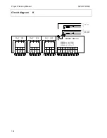
Page 134: ...R20 Circuit diagram K AE1 AE2 BE BA L GND GND Iy 1 2 3 4 5 6 7 8 SIPART DR20 K 6DR2004 1 AC 230 V 6DR2004 2 AC 115 V 6DR2004 4 UC 24 V 1 2 3 4 1 2 3 4 1 2 3 4 PE N L AC 115 V AC 230 V PE N UC 24 V L Slot 3 GW Slot 2 AE4 Slot 1 AE3 134 ...

Page 135: ...Circuit diagram S AE1 AE2 BE BA L GND GND L 1 2 3 4 5 6 7 8 SIPART DR20 S 6DR2001 1 AC 230 V 6DR2001 2 AC 115 V 6DR2001 4 UC 24 V 1 2 3 4 1 2 3 4 1 2 3 4 PE N L AC 115 V AC 230 V PE N UC 24 V L Slot 3 GW Slot 2 AE4 Slot 1 AE3 y y 7 8 135 ...

Page 136: ...alue 0 LA 13 Vertex 1 8 12 5 L1 14 Vertex 2 8 25 L2 15 37 5 L3 Vertex 3 8 16 Vertex 4 8 50 L4 17 Vertex 5 8 62 5 L5 18 Vertex 6 8 75 L6 19 Vertex 7 8 87 5 L7 20 Full scale value 100 LE 21 22 Setpoint limitation Start wva wa SA 23 Setpoint limitation End wve we SE 24 Safety setpoint ws SH 25 26 Alarm value minimum A2 A2 27 Alarm value maximum A1 A1 28 29 A A Response threshold of xd 30 31 Manipulat...

Reviews: