SIPART DR20
Project Planning Manual
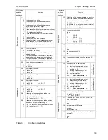
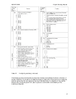
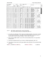
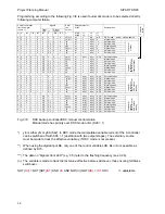
Structuring
switches
and
positions
Function
S1
0
1
2
3
4
5
6
7
8
9
10
Device type
Fixed setpoint controller
Fixed setpoint controller with disturbance
variable feed-forward at input
Fixed setpoint controller with disturbance
variable feed-forward at output
DDC back-up fixed setpoint controller
Slave controller without local/ remote switchover
Slave controller with local/remote switchover and
SPC via the serial interface
Synchronization controller without local/remote
switchover
Ratio controller
Ratio station (only in “K”
version)
Manual/automatic control station and manual
control device, DDC manual control device
Process indicator K: with setpoint value output
Process indicator S with 2nd limit monitor
S2
0
1
2
3
Output structure
K output (0/4 to 20 mA)
S output. two-step controller with 2 outputs for
heating/cooling
S output. three-pos. step controller for motor-
operated devices, internal position feedback
S output. three-pos. step controller for motor-
operated devices. external position feedback
Basic posit
ions
S3
0
1
Mains trequency suppression
For 50 Hz
For 60 Hz
S4
0
1
Input signal from AE1:
0 to 20 mA
4 to 20 mA
S5
0
1
Input signal from AE2:
0 to 20 mA
4 to 20 mA
S6
0
1
Input signal from AE3:
0 to 20 mA
or U, R, P, T
4 to 20 mA
S7
0
1
Input signal from AE4:
0 to 20 mA
or U, R, P, T
4 to 20 mA
S8
0
1
Allocation of the analog inputs to the main
controlled variable X1
AE 1 (0/4 to 20 mA without electrical isolation)
AE 3 (option for I/U, R, P, T)
Analog inputs
S9
0
1
Allocation of the analog inputs to the position
feedback Y
R
or position tracking Y
N
:
AE 2 (0/4 to 20 mA without electrical isolation)
AE 4 (option for I/U, R, P, T)
Table 3/1
Configuring switches
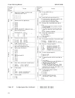
Structuring
switches
and
positions
Function
S10
-2
-1
0
1
Allocation of the analog inputs to the auxiliary
controlled variable X2/command variable X2
(ratio control) or remote setpoint WE:
AE1 (0/4 to 20 mA without electrical isolation)
AE2 (0/4 to 20 mA without electrical isolation)
AE3 (option for I/U, R, P, T)
AE4 (option for I/U, R, P, T)
S11
0
1
2
3
4
5
6
7
Transmitter monitoring
None
X1 - -
X2/wE
-
X1 X2/wE
-
- - Y
R
/Y
N
X1 - Y
R
/Y
N
- X2/wE
Y
R
/Y
N
X1 X2/wE
Y
R
/Y
N
S12
0
1
Root extraction of main controlled variable X1:
No
Yes
S13
0
1
Root extraction of X2:
No
Yes
Analog inputs
S14
0
1
Linearization of main controlled variable X1:
No
Yes
S15
0
1
2
3
4
5
Function of the digital input BE
BL blocking of manipulated output
Si safety value of manipulated
variable y = yS
N
tracking of the output y = yN
CB computer ready signal
BE on serial interface
BLPS
Block parameterization /
structuring
CB without
acknowledgeme
n
t
6
7
8
9
10
11
BL blocking of manipulated output
Si safety value of manipulated
variable y = yS
N
tracking of the output y = yN
CB computer ready signal
BE on serial interface
BLPS
Block parameterization /
structuring
CB with
acknowledgeme
n
t
Analog inputs
S16
0
1
Sense of the digital input BE:
13 to 30 V = logical 1
0 V / open = logical 1
S17
0
1
x-tracking (w = x, wv = xv) in H, N, DDC, BI
and Si operation
No
Yes
S18
0
1
Setpoint w with CB failure:
Local w
Safety setpoint w
s
Setpoint control
S19
0
1
Tracking of the local setpoint wi to the effective
setpoint w
Yes
No
19


