SIPART DR20
Project Planning Manual
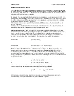
The configuring switch S19 = 1 suppresses tracking of the local setpoint wi and wES of the serial
interface. Thus operation is possible with two or three setpoints. If the switchover via CB is not
required, the digital input should be connected to one of the other control signals via S15 and CB is
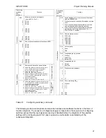
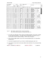
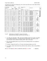
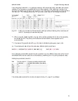
then fixed at 1. The following table (Fig. 3/11) provides a summary of the changed conditions.
Signals
Control commands
front and digital
inputs **)
Front
LED ***)
Digital
output
Effec-
tive
output
Effective setpoint
S19=0
H+N+Si+BL CB INT INT H /RB /RC Y
S17=0
S18=0
=1
=0
=0
=1
=1
=1
Explanations
0
1 0 0 0 0 0 yA(n)
wE
wE
wE
wE
0
0 0 0,5
0 0 1 yA(n)
wi
wi
wS
wS
0
1 1 0,9
0 1 1 yA(n)
wi
wi
wi
wi
0
0 1 1 0 1 1 yA(n)
wi
wi
wi
wi
Automatic mode
1 1
0
0
>
0
1 1 yH
or
wE
x
wE
x
1 0
0
0,5
>
0
1 1 yE
or
wi
x
wS
x
1 1
1
0,9
>
0
1 1 yS
or
wi
x
wi
x
1 0
1
1
>
0
1 1 yBL wi
x
wi
x
Manual, tracking, safety mode or
blocking of output
Fig. 3/11
Follow-up controller with local/remote switchover without tracking of the local setpoint
(S19=1), operation with several setpoints
**) When using the digital input BE, only one of the control variables CB, Si, BL or N is possible
as defined by S15. The priority is Si before BL before N (DDC) when applied via the
serial interface.
***) The data on "Signals front LED" (e.g. 0.5) refer to the flashing frequency (see 3.2.6).
(n) The variable is made to track the last value effective before switchover.
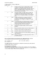
NOT(
RC
) = NOT{NOT(
INT
) AND
CB
AND
NOT(
H
)}
NOT(
RB
) =
INT
OR
H
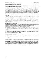
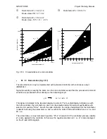
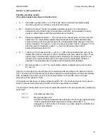
From software version A06 onwards it is also possible to set two different setpoints on the front of
the SIPART DR20 and to select one of the values by switching over or by using a setpoint ramp.
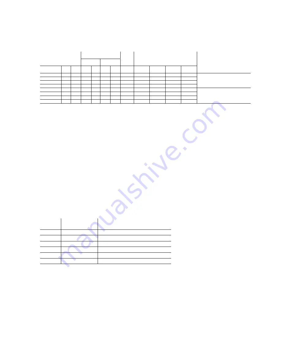
Settings required when used as:
Strs Fixed
setpoint
controller
Process variable indicator with
setpoint transmitter (K version)
S1 5
10
S15
≠
3
≠
3
S18 1
1
S19 1
1
S24 1
1
S42 2
2
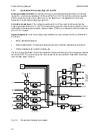
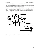
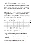
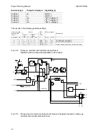
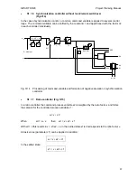
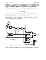
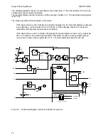
This configuration extends the function of selector 8 (Fig. 2/1, page 11) as follows:
35

