Project Planning Manual
SIPART DR20
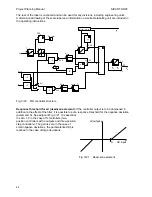
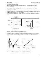
Limitation of controller output signal yA:
(only possible with K controllers and three-position
step controllers with external position feedback, i.e. with S2 = 0 and S2 = 3) Manipulated variable
limitation with parameters ya and ye is only possible in automatic mode. The limits of these
parameters are -10 and + 110 %. It should be noted, however, that the controllers do not output
negative manipulated variable currents and cannot measure negative position feedback signals.
If the manipulated variable yA reaches one of the limits ya or ye in automatic mode, further
integration is suppressed to prevent integral saturation. This ensures that a change in manipulated
variable can be followed immediately if the polarity of the deviation is reversed.
The manipulated variable y can be driven outside the range limits in manual, tracking (DDC) or
safety mode. The last manipulated variable is then transferred in a hitchless manner when
switching back to automatic mode, but only changes to the manipulated variable in the direction
towards the range ya to ye are subsequently executed.
With a two-position controller (S2 = 1), yA is limited to 0 and 100 %. The parameters ya and ye
have a different meaning in this case (see Section 3.2.4).
Manipulated variable limitation is not possible with three-position step controllers with internal
simulation of the position (S2 = 2).
3.2.4
Output Signal Processing and Switchover
The following functions are described in this section:
−
Possible operating modes
−
Priority switchover of manual and tracking mode/blocking
−
Manual manipulated variable yH
−
Position feedback
−
Position display and matching to direction of action
−
Function and direction of action of digital output
−
Special functions of alarm output module
and, depending on the possible output configurations:
−
K output, switchover and switch-off facilities
−
S two-position output with two zones (heating/cooling)
−
S three-position step output for motor-driven actuators with internal position feedback,
minimum positioning pulse length and pause
S three-position step output for motor-driven a
−
ctuators with external position feedback
If controllers are referred to in the following explanations, the ratio station (only as K version), the
manual/automatic control station and the DDC manual control station are included unless special
reference to these devices is specifically made. All information for the K version applies to the
process indicator with setpoint transmitter. Only the information on the special functions of the
alarm module are of interest for the S version.
46

