SIPART DR20
Project Planning Manual
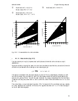
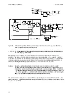
The direction of action of the position display is matched to the process using configuring switch
S33 (see also Figs. 3/24 to 3/32). The signal to be displayed is indicated directly in the basic
position S33 = 0, a reversed display takes place with S33 = 1 (100 % minus value to be displayed).
This display is required if the trends of the position display and the controlled variable are to be in
the same direction with a reversed system. The position display has a resolution of 1 % as a result
of the two-digit display 6. The display range is -9 to + 109 % where values above 100 are
displayed as "h0" to "h9".
The two-digit display 6 contains two points 7.1 and 7.2 (top left and bottom right) which light up if
the associated manipulated variable o
∆
y and -
∆
y are driven.
Function and direction of action of digital output:
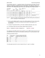
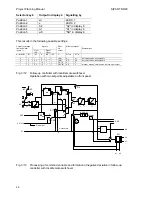
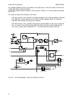
The SIPART DR20 has a digital output (see
Fig. 3/3, page 25) which can be assigned to an operating mode or transmitter fault signal (S34)
and whose NC or NO position can be inverted using S35.
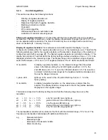
S34 = 0
/RC
Controller not in computer mode
NOT(NOT INT AND CB)
S34 = 1
H
Manual mode (this digital signal indicates the mode "Manual" even if
this has only been prepared and is not. yet effective because of a
priority (e..g.: BI or N)
S34 = 2
/RB
Controller not in computer readiness (lNT or H)
S34 = 3
Must Transmitter fault (collective signal). This fault signal is only output if
S11 is programmed accordingly (Fig. 3/2).
S34 = 4
SES
The digital signal is activated via the serial interface only.
Special functions of the alarm output module:
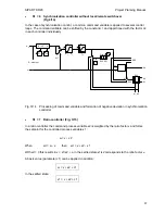
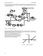
Configuring switch S36 must be set to "1" if a
module 6DR2801-8B (4 digital outputs BA + 1 digital input BE) is used for alarm output. The alarm
outputs A1 and A2, as well as the :
±
∆
y
positioning commands with the S controller, are then
output via the digital outputs of this module. The two output relays in the S controller are set out of
operation.
The parameterization and configuring facility can also be blocked via the digital input BLPS of this
module. If this input is connected to L+, the display "PS" cannot be achieved as preparation for
parameterization or configuring.
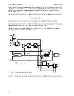
In addition to the described functions, this module also enables a controller with a stepped
output (S controller) to be produced from a standard K device: The K output is effective (Iy = 0/4
to 20 mA) in the standard controller with configuring switch 2 in position 0, the device outputs
switched positioning commands via the
∆
y outputs of this module in all other positions of this
configuring switch.
49

