SIPART DR20
Project Planning Manual
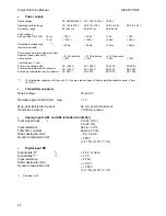
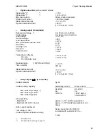
Measuring leads should be twisted and must be routed separately from power cables or screened.
The screen must be connected to one of the M (Ground) connections.
Connection of serial interface and bus driver
5.2.1 Wiring
The max. permissible conductor cross-section for the plug-in screw terminal blocks is 1.5 mm
2
(AWG 14).
The SIPART DR20 is designed with a large EMC to ensure interference free operation. To
maintain a high degree of reliability, we recommend that all inductances (e.g. relays,
motors, contactors) in the vicinity of, or that are connected to the controller, be connected
to suitable suppressors (e.g. RC combinations).
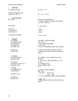
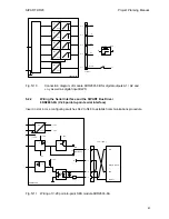
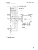
The bus side of the driver is connected to the controller by a ribbon cable attached to a 9-way
subminiature D-plug (x1). Parallel interfaces can therefore be implemented cheaply. V.28 point-to-
point connections are established by a 9-way round cable socket connector. A round cable
attached to a 25-way subminiature D-plug connects the point-to-point side of the bus driver to the
remote system. D-plugs are not supplied with the modules.
Power for the bus driver is supplied via a 10-way terminal block (x2). Jumpers on the 10-way block
(and also on an additional 8-way block (x3)) allow the supply to be configured as required. The 8-
way block x3 is connected in parallel to the 25-way jack x4, which allows the remote system to be
connected to x3 if necessary. The 10-way and 8-way terminal blocks are supplied with the driver.
9-way D-plug for round cable (soldered)
C73451-A347-D35
9-way D-plug for ribbon cable (i.p.c.d.)
C73451-A347-D36
25-way D-plug for round cable (soldered)
C73451-A347-D38
Recommended cables
FLi-Y10 x 1 x 0.14 mm
10 core ribbon cable AWG 26
JE-LiYY 4 x 1 x 0.5 BdSi
core unscreened round cable
Zero volt system:
The SIPART DR20 controller has just one zero-volt conductor M at the field end which is lead out
twice to terminals 6 and 7 of the standard controller. All input and output signals refer to this point.
The power supply connection is electrically isolated from the device. The SIPART DR20 controllers
need not be connected together in the case of systems with non-meshed control loops. In the case
of meshed loops, the M connections of all controllers must be connected individually to a central
star point. This star point may be connected at one position to the protective earth conductor of the
system.
Standard controllers:
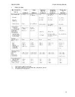
The connection circuits of the standard controller 6DR2001 (S output) and 6DR2004 (K output) are
shown in Fig. 3/1 (page 13).
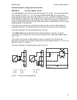
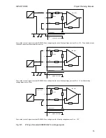
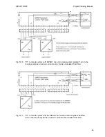
It should be mentioned again that the two analog inputs AE1 and AE2 of the standard controller
are non-floating and can only accept current signals of 0 or 4 to 20 mA. The load of these inputs is
249
Ω
in contrast to the load of the option modules. A voltage drop of max. 5 V occurs across this
load when powering 2-wire transmitters by the SIPART DR20 so that only 15 V are available in the
most unfavorable case as the supply voltage for the transmitter (connection circuits in Fig. 5/2).
71


