Project Planning Manual
SIPART DR20
In the case of highly arced curves, it may be advantageous to improve the approximation by not
applying the corner points of the polygon curve exactly on the function (but exactly on the division
by 8 of the electric axis). The physical values associated with the turning points must then be
entered as parameters L1 to L7. LA and LE must exactly correspond to the start-of-scale and full-
scale values.
100 %
0
U
A
LA
T (°C)
U
E
(mV)
Example:
0 %
Type S (Pt110 Rh-Pt)
500 ... 1500 °C
U
E
5
10
15
500
1000
1500
I
E
1
0
2
3
4
5
6
7
8
n
U
n
mV
T (°C)
15.576
→
LE 1500
14.158
→
L7 1383
12.741
→
L6 1266
11.323
→
L5 1148
9.905
→
L4 1028
8.487
→
L3 903
7.070
→
L2 775
5.652
→
L1 640
4.234
→
LA 500
I
A
L1
L2
L3
L4
L5
L6
L7
LE
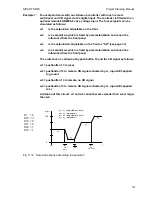
Fig. 6/2
Linearization example (thermocouple type S)
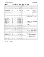
Factory setting of parameters:
the parameter list (Table 6/1) also shows the factory setting of the
parameters. It should be noted that some parameters (ty, SA, SE, A1, A2, yA, yE) determine
values of different functions depending on the configuration of the device. The compatibility of the
factory settings with the selected operating mode should always be checked (see also page 54 for
example).
The output of the process variables in the four-digit display can also be made in engineering units
within the setting range -1999 to 9999 as opposed to the factory setting. It must therefore be noted
of course that all variables which can be output in this display during operation or which influence
the setting of these variables must be set in the same unit (e.g. LA, LE, SA, SE, SH, A2 and A1).
The parameter list contains two constants (c1 and c2), adjustable from -199.9 % to 199.9 %. The
value of the additive constant c1 which can be used in various operating modes always refers to
the set measuring range (0 to 100 %).
The constant c2 is set as a factor (arithmetic value from -1.999 to 1.999).
92

