1 General Part -- Fundamental control technology terms
Manual
10
SIPART DR21
C73000-B7476-C143-08
- Hydraulic actuators with electric oil pump and electrohydraulic positioner. These have a
proportional action and are also driven by continuous controllers.
These types of actuators can be used to implement continuous controls.
- Temperature control loops with diret electric or gas heating and/or cooling systems are
driven by two-postion controllers (on/off controllers). The two-position controllers with the
heating or cooling medium via relays, external contactors or thyristor controllers. The ma-
nipulated variable y is the on/off ratio. These are referred to as discontinuous controls.
D
Controllers and control response
The controlled variable x is compared with the command variable w in the input circuit of the
controller, and the system deviation xd is determined. This is processed with or without a
time response into the output signal. The output signal of the amplifier can directly represent
the manipulated variable y if e.g. proportional-action final control elements are to be driven
by it.
In the case of electric actuators, the manipulated variable is produced by the actuator. The
required positioning inrements are derived from the controller ouptut as a pulse-width-modu-
lated signal by conversion.
Depending on the design of this circuit, the controller has a proportional action (P), a propor-
tional-plus-derivative action (PD), a proportional-plus-integral action (PI) or a proportional-
plus-integral-plus-derivative action (PID).
D
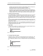
Step function
If a step function is applied to the controller input, a step-forced response results at the out-
put of the controller in accordance with its time response.
xd
t
Figure 1-2 Step function
D
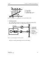
P controller, step-forced response
Characteristic of the P controller are the proportional gain Kp and the working point y
o
. The
working point is defined as the value of the output signal at which the system deviation is
zero. If disturbance variables are present, a steady-state deviation may result depending on
y
o
.
y
t
Kp
·
xd
y
O
Figure 1-3 Step-forced response of P controller
Summary of Contents for SIPART DR21
Page 1: ...SIPART DR21 C73000 B7476 C143 08 1 SIPART DR21 6DR 210 Edition 08 2010 Manual ...
Page 2: ...SIPART DR21 C73000 B7476 C143 08 2 ...
Page 148: ...4 Installation 4 2 Electrical Connection Manual 148 SIPART DR21 C73000 B7476 C143 08 ...
Page 180: ...5 Operation 5 5 CPU self diagnostics Manual 180 SIPART DR21 C73000 B7476 C143 08 ...
Page 242: ...Manual 242 SIPART DR21 C73000 B7476 C143 07 ...

