5 Operation
5.2 Process operation mode
Manual
150
SIPART DR21
C73000-B7476-C143-08
D
Behavior of the controller in the factory setting
SIPART DR21 operates as a fixed value controller in the factory setting.
For safety reasons the online parameters, “proportional action factor Kp” and the “integral
action time Tn” are preset to uncritical values.
It is absolutely essential that these parameters be set to suit the requirements of your
controlled system.
5.2
Process operation mode
D
Control elements
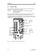
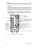
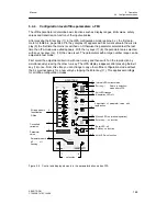
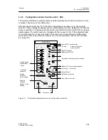
See page 5 for the control and display elements.
The operation of the SIPART DR21 in process mode requires no detailed explanation due to
the design and color scheme of the operating panel, the control elements and the labeling.
D
Actual value
The red vertical LED bargraph (1) and -- with the red x LED (5) -- of the four-digit digital
display (3) lit steadily indicate the actual value.
D
Setpoint
The green vertical LED bargraph (2) and -- with the green w LED (4) -- of the four-digit digital
display (3) lit steadily indicate the setpoint. The green Internal/External key (16) switches
between the internal and external setpoint. The internal setpoint is set with the green
±
Δ
w
adjusting keys (14), (15). The green internal LED (17) signals operation with the internal set-
point, C LED (18) also lights green when there is no CB control signal.
However, a change in the setpoint setting is only possible when the green LEDs (4 and 17)
signal that the four-digit display shows the setpoint and Internal operation is active.
D
Manipulated variable
In the y display (9) the manipulated variable y or, according to the position of the structure
switch S54, the position feedback y
R
or split range y1/y2 is always displayed independently
of the variable output at the analog output AO.
The yellow H/A-key (11) is used to switch between manual and automatic operation. The
yellow manual LED (12) signals by lighting steadily or flashing that manual operation has
been activated. Lighting up of the yellow y external LED (13) signals an external intervention
in the manipulated variable, i.e. a tracking (DDC) , safety or blocking operation. The manipu-
lated variable generally displayed in the y digital display (9) can be adjusted with the yellow
±
Δ
y keys (7), (8) in manual operation. The
±
Δ
y LEDs (10) indicate the output of the posi-
tioning increments in all operating modes of the S-controller.
The alarm LEDs (20) and signal exceeding or dropping below the limit values.
Summary of Contents for SIPART DR21
Page 1: ...SIPART DR21 C73000 B7476 C143 08 1 SIPART DR21 6DR 210 Edition 08 2010 Manual ...
Page 2: ...SIPART DR21 C73000 B7476 C143 08 2 ...
Page 148: ...4 Installation 4 2 Electrical Connection Manual 148 SIPART DR21 C73000 B7476 C143 08 ...
Page 180: ...5 Operation 5 5 CPU self diagnostics Manual 180 SIPART DR21 C73000 B7476 C143 08 ...
Page 242: ...Manual 242 SIPART DR21 C73000 B7476 C143 07 ...

