7 Application examples for configuring the controller
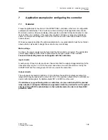
7.1 General
Manual
194
SIPART DR21
C73000-B7476-C143-08
D
Configuring
Structure switches S
All controllers are supplied with the specified factory settings and must be structured to suit
the application during commissioning.
The switch positions for the respective application which deviate from the factory
setting are listed in the examples.
In addition other settings may be necessary due to system-specific criteria.
The following configuration examples have exclusively parallel circuits. Therefore the struc-
ture switches which relate to the serial interface are not specified.
Parameters
onPA and oFPA
The controllers must be adapted in every case using the system data. The factory setting of
the control parameters must be selected so that the control loop does not tend to oscillate
even under worst case conditions (Kp = 0, 1, Tn = 9984 s). Kp and Tn or y0 and if necess-
ary Tv and AH must be set.
Control algorithm
All configuration examples (except Z1) are shown for PI or PID behavior. Switching to P or
PD behavior is possible with a digital input signal (structure switch S27). In the SIPART
DR21 as an S-controller, a P-or PD-controller operation is only possible with external posi-
tion feedback (S2=3).
Summary of Contents for SIPART DR21
Page 1: ...SIPART DR21 C73000 B7476 C143 08 1 SIPART DR21 6DR 210 Edition 08 2010 Manual ...
Page 2: ...SIPART DR21 C73000 B7476 C143 08 2 ...
Page 148: ...4 Installation 4 2 Electrical Connection Manual 148 SIPART DR21 C73000 B7476 C143 08 ...
Page 180: ...5 Operation 5 5 CPU self diagnostics Manual 180 SIPART DR21 C73000 B7476 C143 08 ...
Page 242: ...Manual 242 SIPART DR21 C73000 B7476 C143 07 ...

