7 Application examples for configuring the controller
7.3 Configuration examples
Manual
212
SIPART DR21
C73000-B7476-C143-08
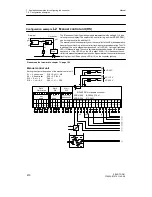
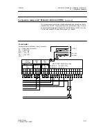
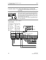
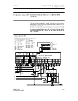
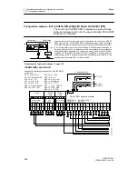
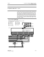
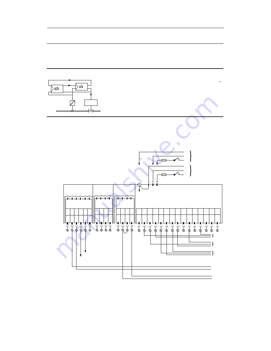
Configuration example
L3
control unit (LG) with slave controller (FR)
LG operates as a setpoint transmitter and manual control unit
with S-output.
With the LG the setpoint and the S-output of the slave controller can be remote con-
trolled. The FR has priority with respect to setpoint and manual operation. The set-
point of the FR can only be set with the LG when the LED (17) internal, LED (18)c
and LED (4) w display are alight. It is recommended to switch off the setpoint ramp
on the FR. Before switching over to setpoint presetting from the FR, you have to
wait for the setpoint set on the LG (max. 6 s).
Parallel to the FR, the process variables setpoint, controller variable and position
feedback can be displayed on the LG. x2 must be structured with S16 on the LG
for the analog x value display.
Drive
±
Δ
y
w
x
F-controller
Control unit
w
w
±
Δ
y
w
Please read the foreword to chapter 7.1, page 193
Control unit (LG)
Setting the structure switches of the control unit:
S1 = 4, control unit
S30 = 2, --yBL
!
DI2
S2 = 0, S-controller i.Rf.
S42 = 2, wi: int
$
ext
S15 = 0, x1 = 0
S49 = 1
S17 = 1, we
!
AI1
S54 = 1, yR display
S19 = 3, yR
!
AI3
S56 = 2, w
!
AO
S22 = 1, Opt. Position 3
S57=1,
±
Δ
y
!
DO1/2
S23 = 1, CB
!
DI1
S58 = 3, RB
!
DO3
S25 = 0, N = 0
S60 = 4, H
!
DO4
S26 = 0, Si = 0
S62 = 5, A1
!
DO5
S29 = 2, +yBL
!
DI2
S63 = 6, A2
!
DO6
AI1
--
PE
N
L
PE
N
L
UC 24 C
AC 115 V
AC 230 V
AI1
+
AI2
--
AI2
+
DI1 DI2
L+ AO
1
2
3
4
5
6
7
8
9
10 11
12
Slot 1
AI3
Slot 2
AI4
Slot 3
DI3 DO
3
DO
6
DI4
DO
4
DO
5
1 2 3 4
5
6
not
used
1
2
3 4
Option module
6DR2800-8J
L
+
Δ
y
13 14 15
--
Δ
y
SIPART DR21 standard controller
6DR2100-5
(AC230 V/115 V)
6DR2100-4
(UC 24 C)
1 2
3 4
R
--
+
Option module
6DR2801-8E
A1
A2
¡
©
¢
£
¥
¦
¤
GND
GND GND
DO
1
DO
2
Summary of Contents for SIPART DR21
Page 1: ...SIPART DR21 C73000 B7476 C143 08 1 SIPART DR21 6DR 210 Edition 08 2010 Manual ...
Page 2: ...SIPART DR21 C73000 B7476 C143 08 2 ...
Page 148: ...4 Installation 4 2 Electrical Connection Manual 148 SIPART DR21 C73000 B7476 C143 08 ...
Page 180: ...5 Operation 5 5 CPU self diagnostics Manual 180 SIPART DR21 C73000 B7476 C143 08 ...
Page 242: ...Manual 242 SIPART DR21 C73000 B7476 C143 07 ...


