2 Technical Description
2.4 Design
Manual
24
SIPART DR21
C73000-B7476-C143-08
2.4
Design
D
Standard controller
The process controller has a modular structure and is therefore maintenance friendly and
easy to convert- and retrofit.
The standard controller consists of
-
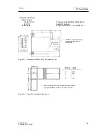
the front module with the control- and display elements
-
the backplane module with the power supply unit
-
the plastic housing with four slots for optional modules
D
Front module
The front module accommodates the control- and display elements, the CPU (Central Pro-
cessing Unit) and the connectors for the backplane- and options modules.
It is operated by a membrane keyboard with IP64 degree of protection. The front design is
based directly on the SIPART DR 20/22/24-controller-family with color coded assignment of
the display- and control elements.
For better monitoring of the process, SIPART DR21 has user-friendly analog displays for the
setpoint- and actual value display, a four-digit digital display which can be set for setpoint,
actual value and alarms (depending on the controller setting), a two-digit digital display for
the manipulated variable y, numerous control keys and indicator diodes for various status
signals.
The tag plate and the scales for the analog displays are replaceable.
D
Backplane module with power supply unit
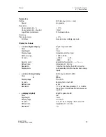
The following signal connections are accessible through the backplane.
- 2 analog inputs AI1, AI2, potential-bound to GND, 0/4 to 20 mA
- 1 analog output AO, potential-bound to GND, 0/4 to 20 mA
- 2 digital o
Δ
y,-
Δ
y, potential-free via relay contacts
- 2 digital inputs DI1, DI2, for 24V-logic, function can be set
- 2 digital outputs DO1, DO2, for 24V- logic, function and direction can be set
- 1 Voltage output L+ to the transmitter supply
The power supply is located in a die-cast housing on the backplane module. The heat loss is
transferred to the back of the controller by cooling fins.
A DIN rail can be mounted for connecting a powerful coupling relay module.
The power supply unit is high powered and offers a total 200 mA current for:
- supplying the analog output (0/4 to 20 mA)
- Active digital outputs (up to 6 digital outputs)
- L+-output for supplying two-wire-transmitters
- supplying the interface module
Summary of Contents for SIPART DR21
Page 1: ...SIPART DR21 C73000 B7476 C143 08 1 SIPART DR21 6DR 210 Edition 08 2010 Manual ...
Page 2: ...SIPART DR21 C73000 B7476 C143 08 2 ...
Page 148: ...4 Installation 4 2 Electrical Connection Manual 148 SIPART DR21 C73000 B7476 C143 08 ...
Page 180: ...5 Operation 5 5 CPU self diagnostics Manual 180 SIPART DR21 C73000 B7476 C143 08 ...
Page 242: ...Manual 242 SIPART DR21 C73000 B7476 C143 07 ...

