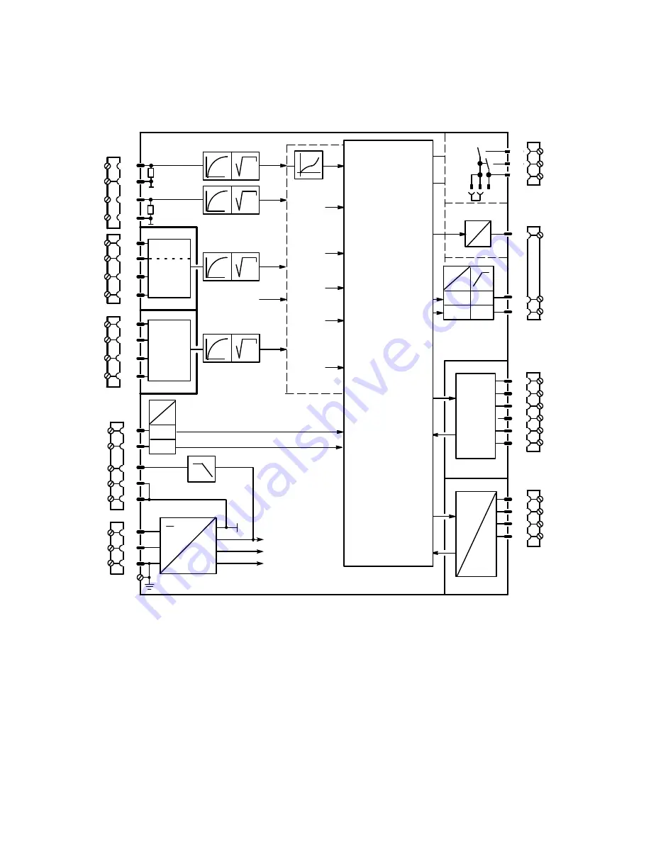
Block diagram
10
AI4A
S13
AI3A
t
S11
AI1A
S6
2
1
4
3
t
AI3
Slot 1
S7
Slot 2
I,U,R
I,U,R
AI4
Options
0 %
Y
N
S18
DI1
DI2
24 V
5 V
L+
GND
GND
N
L
M
+24 V
+5 V
U
REF
S14
t
S21
S57
DO7
DO8
24 V
5 V
I
U
I
S56
15
14
13
8
7
S22
Z
S20
Y
R
S19
w
EA
/x3
S17
x2
S16
x1
S15
4DO 24V
2DI
2DO Rel
5DI
Slot 3
S84 to S91
4/2
4/7
4/8
4/3
Slot 4
SES
5 V
DO2
DO1
+
Δ
y
--
Δ
y
AO/Jy
I
Options
Txd
Rxd
S3
=
1/4
1/3
1/2
1/1
2/4
2/3
2/2
2/1
5
6
12
11
9
PE
3/6
3/5
3/4
3/3
3/2
3/1
∽
AI1
--
+
AI2
UNI
S8 to S10
t
S12
AI2A
S4
S5
249
249
--
+
Basic
settings
S1 to S3
Analog inputs
S4 to S21
Configuration of slot 3
S22
Digital inputs
S23 to S41
Setpoint tracking
S42 to S45
Control algorithm
S46 to S48
Y switchover
S49 to S53
Y indicator
S54 to S55
Analog output
S56
Switching output
S57
Digital outputs
S58 to S75
Limit monitors
S76 to S80
x/w indicator
S81
Restart
conditions
S82 to S83
Serial interface
S84 to S91
L
SIPART DR21
C73000-B7476-C143-08
6
Summary of Contents for SIPART DR21
Page 1: ...SIPART DR21 C73000 B7476 C143 08 1 SIPART DR21 6DR 210 Edition 08 2010 Manual ...
Page 2: ...SIPART DR21 C73000 B7476 C143 08 2 ...
Page 148: ...4 Installation 4 2 Electrical Connection Manual 148 SIPART DR21 C73000 B7476 C143 08 ...
Page 180: ...5 Operation 5 5 CPU self diagnostics Manual 180 SIPART DR21 C73000 B7476 C143 08 ...
Page 242: ...Manual 242 SIPART DR21 C73000 B7476 C143 07 ...

