1 HL1
Manual
SIPART DR21
C73000-B7476-C143-08
9
1
General Part -- Fundamental control technology terms
D
Control loop
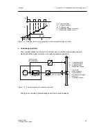
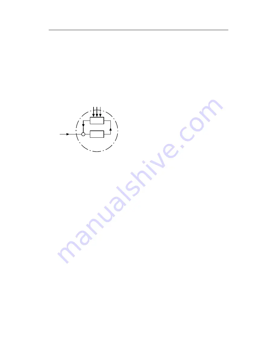
The function of a closed-loop control is to bring the output variable x of a controlled system
to a predefined value and to retain this value even under the influence of disturbance
variables z. The controlled variable x is compared with the command variable w. The
resulting system deviation xd = w -- x is processed in the controller to the manipulated
variable y which acts on the controlled system.
The controlled variable x is measured cyclically in a digital control.
w
Command variable
x
Controlled variable
xd System deviation
y
Manipulated variable
z
Disturbance variable
1
Controlled system
2
Control equipment
z1 z2 z3
1
2
y
x
xd
w
-
+
Figure 1-1 Function diagram of control loop
D
Sensors and transmitters
The controlled variable can be any physical variable. Frequently controlled variables in pro-
cess engineering are pressure, temperature, level and flow.
In most process engineering applications, the process variables are measured using sensors
and transmitters with a standardized signal output (0 to 20 mA or 4 to 20 mA). The standard-
ized signal can be connected to several process process devices (loop between e.g. re-
corder/indicator/controller). Temperature sensors such as resistance thermometers or ther-
mocouples, as well as resistance transmitters, can be connected directly to the controller
using appropriate input cards (options).
D
Final control elements and actuators
In process engineering applications, the manipulated variale y primarily acts on the con-
trolled system via a valve, a butterfly valve or another mechanical means of adjustment.
Three types of drive are possible for actuating such final control elements:
- Pneumatic actuators with compressed air as the auxiliary energy and electropneumatic
signal converters or electropneumatic positioners. These have a proportional action and
are driven by continuous controllers.
- Electric actuators, consisting of an electric motor and gear unit. These have an integral
action and are driven by three-position step controllers. Electric actuators are also poss-
ible with an integrated (series-connected) positioner and then have a proportional action
and can be driven by continuous controllers.
Summary of Contents for SIPART DR21
Page 1: ...SIPART DR21 C73000 B7476 C143 08 1 SIPART DR21 6DR 210 Edition 08 2010 Manual ...
Page 2: ...SIPART DR21 C73000 B7476 C143 08 2 ...
Page 148: ...4 Installation 4 2 Electrical Connection Manual 148 SIPART DR21 C73000 B7476 C143 08 ...
Page 180: ...5 Operation 5 5 CPU self diagnostics Manual 180 SIPART DR21 C73000 B7476 C143 08 ...
Page 242: ...Manual 242 SIPART DR21 C73000 B7476 C143 07 ...

