3
Functional description of the structure switches
3.6
Controller output structures (S2, S49 to S55)
Manual
SIPART DR21
C73000-B7476-C143-08
99
D
S2 = 2:
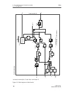
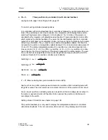
Three-position step controller (S) with internal feedback
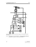
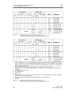
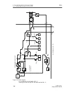
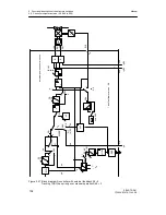
see figure 3-25, page 100 and figure 3-26, page 101
To control I-acting motorized actuating drives.
In S-controllers with internal feedback the K-controller is followed by an internal position con-
troller. The positioning control circuit consists of a comparator with following three-position
switch with hysteresis and an integrator in the feedback. The I-function of the actuator is
simulated by the integrator with adjustable actuating time tY (parameterization mode onPA)
which replaces the position feedback. To ensure the internal integrator and the K-controller
output do not drift apart or into saturation in time, both are set back rhythmically by the same
amount (synchronized). The y-output is only a relative manipulated variable. It is therefore
not possible to perform a manipulated variable limiting of Y
A
and an absolute value preset of
Y
E
und Y
S
. The safety manipulated variable Y
S
is specified as a direction-dependent con-
tinuous contact. At Y
S
≤
50 % (oFPA) -
Δ
y switches, at Y
S
> 50 %, +
Δ
y switches to continu-
ous contact so that the end positions of the actuator represent the safety position. The posi-
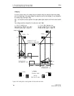
tion controller has an adjustable minimum pulse length (tE) and-pause (tA) with which the
response threshold of the position controller is set indirectly:
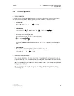
- Switching on
Aee = 2
100 %
⋅
tE
tY
- Switching off
Aea =
100 %
⋅
tE
tY
- Hysteresis
Aee -- Aea =
100 %
⋅
tE
tY
- Pause
Aa =
100 %
⋅
tA
tY
- tY = tP, tM set actuating time (parameterization mode onPA)
Aee must be set up after a pulse pause at least as a deviation until an actuating pulse with
length tE is output. Aea can remain as a constant control error of the position control circuit.
Aa can be set up after an actuating pulse as a deviation until an actuating pulse is output in
the same or opposite direction. When time tA has expired, the position controller reacts
accordingly to the set tE.
Setting criteria of tA and tE, see chapter 6.3, page 183.
The position feedback y
R
is only used to display the manipulated variable in S-controllers
with internal feedback. If it is not connected, S54 is set to 3, the y-display (9) is then dark.
Summary of Contents for SIPART DR21
Page 1: ...SIPART DR21 C73000 B7476 C143 08 1 SIPART DR21 6DR 210 Edition 08 2010 Manual ...
Page 2: ...SIPART DR21 C73000 B7476 C143 08 2 ...
Page 148: ...4 Installation 4 2 Electrical Connection Manual 148 SIPART DR21 C73000 B7476 C143 08 ...
Page 180: ...5 Operation 5 5 CPU self diagnostics Manual 180 SIPART DR21 C73000 B7476 C143 08 ...
Page 242: ...Manual 242 SIPART DR21 C73000 B7476 C143 07 ...


