Mechanical construction
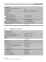
• Cable gland for NPT bushing in the NPT adapter
NOTE: To avoid damage to the device, the NPT adapter must
be held in place while the NPT gland is screwed into the NPT
adapter.
68 Nm (50 ft lb)
• Screw cap made of plastic
2.5 Nm (1.8 ft lb)
• Screw cap made of metal
4 Nm (3 ft lb)
• Pressure gauge block fixing screws
6 Nm (4.4 ft lb)
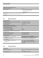
Pressure gauge
• Material pressure gauge
Plastic, Mechanics brass
Stainless steel, Mechanics brass nickel-plated
Stainless steel, Mechanics stainless steel 316
• Material pressure gauge block
Anodised aluminium
Stainless steel 316
• Degree of protection
Plastic, Mechanics brass, Pressure gauge block anodised
aluminium
IP31
Stainless steel, Mechanics brass nickel-plated, Pressure
gauge block anodised aluminium
IP44
Stainless steel, Mechanics stainless steel 316, Pressure
gauge block stainless steel 316
IP54
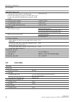
Connections, electrical
• Screw terminals
2.5 mm
2
AWG30-14
• Cable gland
M20x1.5 or 1/2-14 NPT with NPT adapter
Connections, pneumatic
G¼ or ¼-18 NPT
9.6
Controller
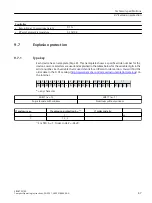
Controller
Control unit
• Five-point controller
Adaptive
• Deadband
Adjustable peak value
± 0.1 to 3%, plus hysteresis (half of the dead‐
band, but at least 0.2%)
Minimization of the peak value
Always active
Analog input (AI), terminal 6 and 7
• Sampling interval
50 ms
• Resolution
0.05%
Position detection
• Sampling interval
10 ms
Technical specifications
9.6 Controller
SIPART PS100
46
Compact Operating Instructions, 05/2021, A5E50188940-AA


