Connect
6.1 Connect electrically
SIPART PS2 with PROFIBUS communication
Operating Instructions, 09/2007, A5E00127926-07
77
2.
Open the enclosure of the positioner by unlatching the four cover screws.
3.
Insert the prepared bus cable through the cable inlet.
4.
Fasten the shield using the clamp and both the screws on the enclosure.
5.
Tighten the cable inlet.
6.
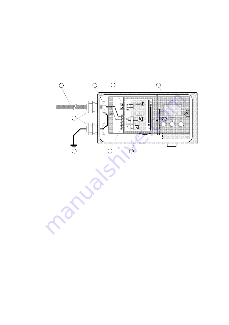
Connect the red and the green wires to terminals 3 and 7 of the motherboard as shown in
the following picture. The polarity does not play any role here.
Figure 6-3
Connecting the bus cable for the positioner without a flameproof enclosure
①
Bus cable
②
Cable clamp
③
Motherboard
④
Module cover
⑤
Sign
⑥
Terminal strip
⑦
Earth potential
⑧
Cable glands
Installing the bus cable for versions with flameproof enclosures
Proceed as follows to install the bus cable:
1.
Strip the bus cable.
2.
Open the safety catch and unscrew the screw cap to open the positioner.
3.
Insert the prepared bus cable through the Ex d certified cable inlet. Follow the
corresponding guidelines if you are using a conduit piping system.
4.
Fasten the shield on the adapter using the clamp and both the screws.
5.
Tighten the Ex d certified cable inlet.


