Description
3.4 Device components
SIPART PS2 with PROFIBUS communication
26
Operating Instructions, 09/2007, A5E00127926-07
3.4.4
Pneumatic connections
3.4.4.1
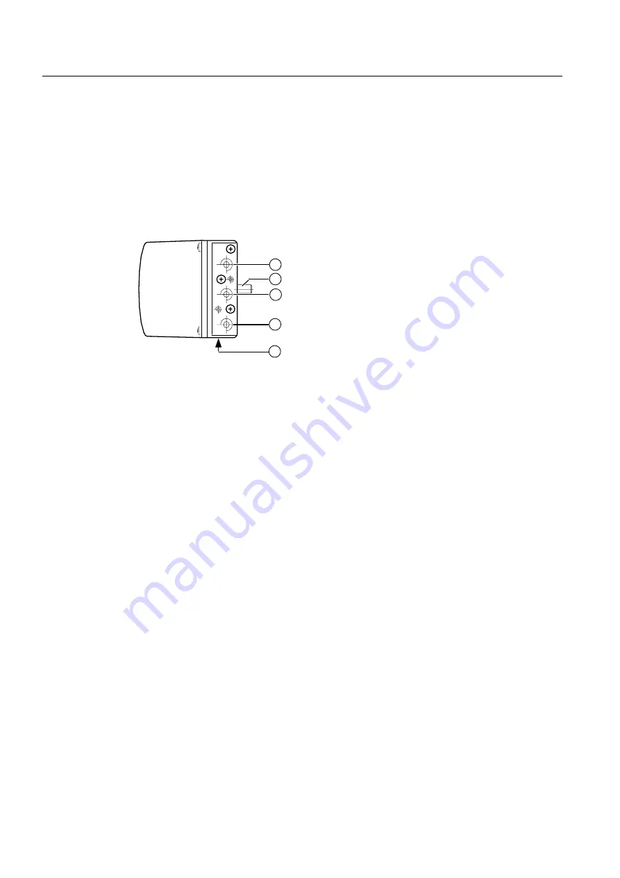
Pneumatic connection on the standard controller
Structure
The pneumatic connections are provided on the right side of the positioner.
Figure 3-9
Pneumatic connection on the standard controller
①
Actuating pressure Y1 for single and double-acting actuators
②
Feedback shaft
③
Supply air P
Z
④
Actuating pressure Y2 for double-acting actuators
⑤
Exhaust air outlet with an attenuator at the bottom side of the device


