Description
3.4 Device components
SIPART PS2 with PROFIBUS communication
Operating Instructions, 09/2007, A5E00127926-07
27
3.4.4.2
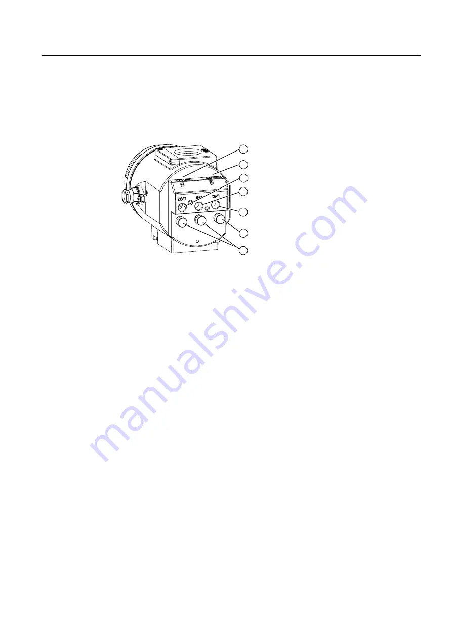
Pneumatic connection in the flameproof enclosure
Structure
The pneumatic connections are provided on the right side of the positioner.
Figure 3-10 Pneumatic connection in the flameproof enclosure
①
Restrictor Y2
*)
⑤
Actuating pressure Y1
②
Restrictor Y1
⑥
Exhaust air outlet E
③
Actuating pressure Y2
*)
⑦
Enclosure ventilation (2x)
④
Supply air P
Z
*) for double-acting actuators
3.4.4.3
Pneumatic connection versions
Overview
For the integrated attachment for single-action linear actuators, the following pneumatic
connections are provided at the rear side of the standard controller:
●
Actuating pressure Y1
●
Exhaust air outlet
These connections are sealed with screws when the device is delivered.
The exhaust air outlet is corrosion-resistant for the blanketing of the pick-up room and the
spring chamber with dry instrument air.
The following overview diagram shows the pneumatic connection versions for different
actuator types, regulating action and safety position after an auxiliary power supply failure.


