Description
3.4 Device components
SIPART PS2 with PROFIBUS communication
Operating Instructions, 09/2007, A5E00127926-07
29
3.4.5
Purge air switching
Note
Equipment
Versions with flameproof enclosures are not equipped with purge air switching.
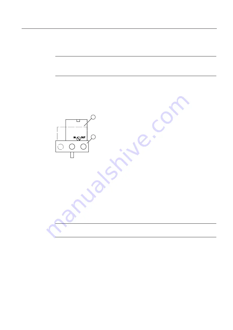
When the enclosure is open, the purge air switch above the pneumatic terminal strip on the
pneumatic block can be accessed.
●
In the IN position, the enclosure is flushed from inside with a small volume of clean and
dry instrument air.
●
In the OUT position, the purge air is directly directed towards outside.
Figure 3-12 Purge air switch on the pneumatic block; view of the positioner on the pneumatic
connection side when the cover is open
①
Purge air switch
②
Pneumatic terminal strip
3.4.6
Restrictors
Note
The exhaust air valve is always open in the de-energized state.
●
Reduce the air output to achieve actuating times of T > 1.5 s for small actuators. Use
restrictors Y1 ① and Y2 ② for this purpose.
●
When turned clockwise, they reduce the air output and finally shut it off.
●
In order to set the restrictors, we recommend closing them and then opening slowly.
●
In case of double-acting valves, ensure that both restrictors have approximately the same
setting.


