


Operating Instructions SIPLUS CMS4000 IFN VIB-A
Preface
1
Product Overview
2
SIPLUS
CMS4000
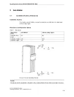
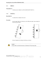
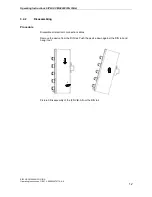
Installation
3
Interface Node
IFN VIB-ACC (IFN VIB-A)
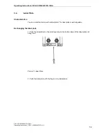
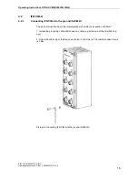
Wiring
4
6AT8000-1BB00-4XA0
Commissioning and Diagnosis
5
Technical Data
6
Appendix
7
Operating Instructions - English
Release 2014-11
SIPLUS CMS4000 IFN VIB-A
Operating Instructions, 11/2014, A5E02297871A-AA
1
Siemens Parts


