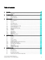
Table of contents
SIPLUS HCS4200 PROFINET/PROFIBUS DP
4
Operating Instructions, 07/2019, A5E35066204A/006
5.5
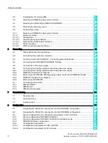
Installing the I/O module (PM) ............................................................................................... 58
5.6
Mounting a POM4220 power output module ......................................................................... 59
5.7
Mounting and dismantling CIM4210C PROFINET ................................................................ 60
5.8
Mounting the blanking covers ................................................................................................ 61
5.9
Double frame setup ................................................................................................................ 61
5.10
Mounting a POM4320 power output module ......................................................................... 63
5.10.1
Busbar mounting .................................................................................................................... 63
5.10.1.1
Preparations ........................................................................................................................... 63
5.10.1.2
Adjusting the busbar adapter ................................................................................................. 64
5.10.1.3
Mounting the POM (busbar adapter) ..................................................................................... 66
5.10.2
Panel mounting ...................................................................................................................... 67
5.10.2.1
POM mounting (panel mounting) ........................................................................................... 67
6
Connecting ........................................................................................................................................... 69
6.1
Safety information and guidelines .......................................................................................... 69
6.2
Connecting the protective conductor ..................................................................................... 71
6.3
Combined mode with POM4320 - Connecting system interfaces ......................................... 74
6.4
Connecting the PROFINET/PROFIBUS fieldbus ................................................................... 76
6.5
Connect 24 V DC power supply ............................................................................................. 77
6.6
Connecting the heating elements and three-phase line supply ............................................. 79
6.6.1
Connecting the heating elements and three-phase line supply ............................................. 79
6.6.2
POM4220 Lowend block diagram .......................................................................................... 86
6.6.3
Block diagram POM4220 Midrange phase angle control and POM4220 Flexible ................ 87
6.6.4
POM4220 Highend block diagram ......................................................................................... 88
6.6.5
Block diagram POM4320 ....................................................................................................... 93
6.7
Connecting I/O modules ........................................................................................................ 94
6.7.1
PM4000 DI/DO ....................................................................................................................... 94
6.7.2
PM4000 U/I ............................................................................................................................ 96
6.7.3
PM4000 Temperature ............................................................................................................ 98
7
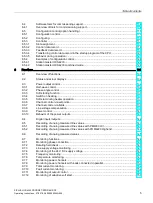
Commissioning .................................................................................................................................... 101
7.1
Requirements ....................................................................................................................... 101
7.2
Commissioning..................................................................................................................... 101
7.3
Insulation test ....................................................................................................................... 102
8
Configuration ....................................................................................................................................... 103
8.1
Integrating the HCS4200 components into the PROFINET configuration ........................... 103
8.2
Integrating the HCS4200 components into the PROFIBUS configuration .......................... 104
8.3
Device configuration and configuration parameters in the TIA Portal ................................. 105
8.3.1
Device configuration PROFINET HCS4200 ........................................................................ 105
8.3.2
Device configuration PROFINET HCS4200 combination mode .......................................... 106
8.3.3
PROFIBUS device configuration.......................................................................................... 107
8.3.4
Configuration parameters .................................................................................................... 108
8.3.4.1
Configuration parameters for CIM and POM ....................................................................... 108
8.3.4.2
Configuration parameters for I/O modules ........................................................................... 112
Summary of Contents for SIPLUS HCS Series
Page 1: ...SIPLUS HCS4200 PROFINET PROFIBUS DP ...
Page 2: ......

