background image


SIPLUS HCS3200  
Operating Instructions, 07/2014, A5E31278506C/002 

45


Communication 

9.1


Cyclic data transfer 

Communication between the DP master and heating controller is performed exclusively via 

cyclic data. 
You can access the cyclic data in the PLC software via the inputs (message data) and the 

outputs (control data). 

9.2


Cyclic input data 

The cyclic input data can be addressed in the S7 through the process image or I/O 

commands. 

Process image inputs (PII) 

The process image for the inputs PII contains the status information for the individual 

modules. All addresses are specified as an offset relative to the base address 0.0. The 

actual addresses are obtained from the configuration of the overall system. 

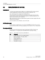
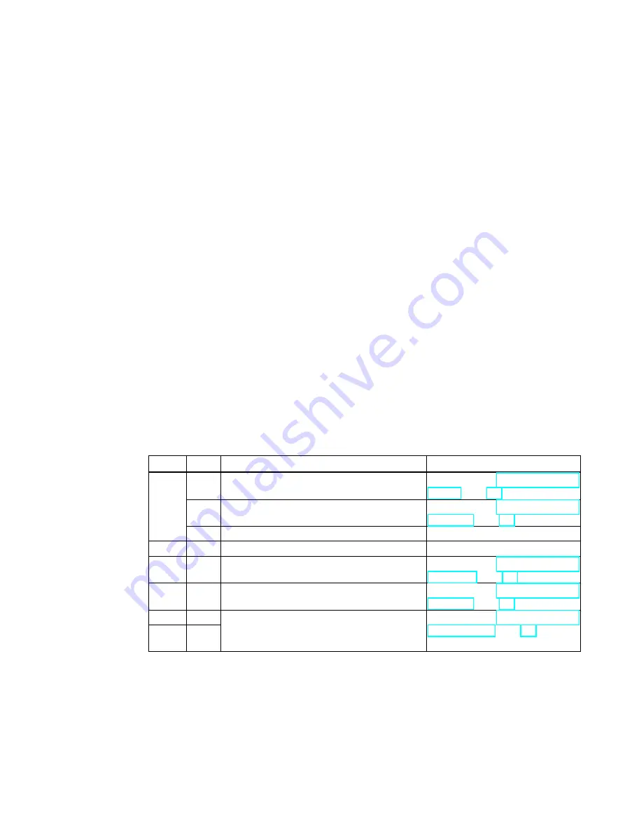
Table 9- 1 

Addressing of inputs 

Byte 

Bit 

Meaning 

Description 


= 0: Heating switched off 

= 1: Heating switched on 

Refer to section Power output 

control (Page 39) 

= 0: Line voltage compensation is not active 

= 1: Line voltage compensation is active 

Refer to section Line voltage com-

pensation (Page 42) 

2 ... 7  0 (reserved) 


0 (reserved) 


Temperature measurement in °C 

Refer to section Temperature 

monitoring (Page 43) 


Factor for line voltage compensation in % 

Refer to section Line voltage com-

pensation (Page 42) 


Voltage measured value Lxy 
 

Refer to section Line supply volt-

age monitoring (Page 41) 


Summary of Contents for SIPLUS HCS3200

Page 1: ......

Page 2: ......

Page 3: ...__________________ ___________________ ___________________ ___________________ Heating Control Systems Heating control system SIPLUS HCS3200 Operating Instructions 07 2014 A5E31278506C 002 Introduction 1 Safety notes 2 Description 3 Application planning 4 Mounting 5 Connection 6 Commissioning 7 Functions 8 Communication 9 Error handling 10 Service and maintenance 11 Technical data 12 Appendix A ...

Page 4: ...y by personnel qualified for the specific task in accordance with the relevant documentation in particular its warning notices and safety instructions Qualified personnel are those who based on their training and experience are capable of identifying risks and avoiding potential hazards when working with these products systems Proper use of Siemens products Note the following WARNING Siemens produ...

Page 5: ... the delivery 17 4 3 Requirements regarding the mounting location 18 5 Mounting 21 5 1 Preparations 21 5 2 Mounting the device 22 5 3 Final work 23 6 Connection 25 6 1 Preparations 25 6 2 Block diagram 26 6 3 Connection element locations 27 6 4 X1 mains connection grounding 28 6 5 X2 heating element connection 30 6 6 X3 X4 PROFIBUS DP 24 V DC 32 6 7 RS232 interface 34 7 Commissioning 35 7 1 Requir...

Page 6: ... 3 Cyclic output data 46 9 4 Diagnostics data 47 10 Error handling 49 10 1 Status and fault display with LEDs 49 10 2 Fault reporting through diagnostics data 50 11 Service and maintenance 51 11 1 Maintenance work 51 11 2 Firmware update 52 11 3 Fuse replacement 54 11 4 Fan replacement 57 11 5 Replacing the device 60 11 6 Recycling and disposal 60 12 Technical data 61 12 1 Technical specifications...

Page 7: ...owing specialist fields Operators project engineers programmers Electrically skilled personnel who assemble connect and start up the device Required basic knowledge These operating instructions require prior knowledge of programming an S7 controller or SIMOTION Knowledge of working with the PROFIBUS DP fieldbus is also necessary History The following earlier release versions of these operating ins...

Page 8: ...Introduction 1 1 Introduction SIPLUS HCS3200 8 Operating Instructions 07 2014 A5E31278506C 002 ...

Page 9: ...g symbols on the device WARNING Electric shock hazard May cause death or serious injury When this warning symbol appears on the device you must consult the operating instructions for the device The operating instructions contain information about the potential risks and enable you to recognize risks and implement countermeasures Note before connecting the device WARNING Electric shock hazard May c...

Page 10: ... it against switching on again Before working on the heating control system or the connected components ensure the system is disconnected Fuse replacement NOTICE Use only the prescribed fuse types If you operate a heating controller with unapproved fuses the device could be destroyed Repairs WARNING No user serviceable parts May cause death or serious injury Incorrectly performed repairs may resul...

Page 11: ...ty developments regarding your products For information on this topic refer to http support automation siemens com Here you can register for a product specific newsletter For the secure operation of a plant machine however it is necessary to integrate the automation components in a full IT security concept for the entire plant machine that represents the state of the art in IT technology You can f...

Page 12: ...Safety notes 2 2 IT security SIPLUS HCS3200 12 Operating Instructions 07 2014 A5E31278506C 002 ...

Page 13: ...200 heating controller Features 9 power outputs with a maximum switching power of 4 kW at 400 V AC Total switching power of the device 25200 W 15 A fuse per power output internally accessible Connection of the line voltage heating elements and PROFIBUS DP 24V DC via connectors underneath the de vice Diagnostics per power output for detecting internal and external faults Internal temperature monito...

Page 14: ...em operating status 2 rotary switches for setting the address of the PROFIBUS DP interface X3 PROFIBUS DP and 24 V DC supply X2 For controlling up to 9 heating elements X1 Line voltage and protective earth PE Lower fuse block for fuses F111 left to F119 right along the incoming lines for heating ele ments 1 to 9 Upper fuse block for fuses F101 left to F109 right along the outgoing lines for heatin...

Page 15: ...DP fieldbus with the SIMATIC S7 controller A complete system includes the following components HCS3200 heating controller Higher level control through SIMATIC S7 automation system with integrated interface for PROFIBUS DP or SIMOTION PROFIBUS DP Cabling Heat emitter array HMI panel optional System configuration The following diagram shows an example of the interaction between the system components...

Page 16: ...Description 3 4 System configuration SIPLUS HCS3200 16 Operating Instructions 07 2014 A5E31278506C 002 ...

Page 17: ...t the necessary protection against shock and impact 4 2 Unpacking and checking the delivery Unpacking the device 1 Unpack the device and the supplied components 2 Check the shipment for completeness 3 Make a visual check of the device and the components for transport damage Keep the packaging material in case you have to return the device Scope of delivery HCS3200 device Mounting hardware Compact ...

Page 18: ...15g 11 ms 3 shocks axis Relative humidity at 25 C during operating maximum 95 Relative humidity at 50 C during operating maximum 50 Incoming supply cabling WARNING Electric shock hazard May cause death or serious injury The line voltage to which the device is connected must have a disconnecting means The disconnecting means must be easily accessible and uniquely assigned to the device It is recomm...

Page 19: ...es are equivalent check with the manufacturer of the lightning protector The lighting protector must be installed and used in accordance with the instructions of the manufacturer With a lightning protector the following interference immunity in accordance with IEC 61000 4 5 is achieved 1 0 kV symm with Ri 2 Ω evaluation criterion B 2 0 kV unsymmetrical with Ri 12 Ω evaluation criterion B Without a...

Page 20: ...Application planning 4 3 Requirements regarding the mounting location SIPLUS HCS3200 20 Operating Instructions 07 2014 A5E31278506C 002 ...

Page 21: ...s up to around 80 C Minimum clearances Maintain the following minimum clearances from other devices Figure 5 1 Clearances for mounting an HCS3200 Note Natural convection must be possible above and below the device A clearance of 200 mm must be observed When two heating controllers are mounted one above the other you must ensure that the heat emitted from the lower device is routed past the upper d...

Page 22: ...acket horizontal mounting on the device Mounting bracket vertical mounting on the device Figure 5 2 Position of the mounting brackets Fixing the mounting brackets Screw the 4 mounting brackets in the required positions vertical or horizontal on the corners of the device Mounting installing the device When attaching to a wall Make sure that the wall can support the total weight of the device Permit...

Page 23: ...CS3200 Operating Instructions 07 2014 A5E31278506C 002 23 5 3 Final work The cage clamps of the fuse holder may have loosened during transport We recommend that you tighten the cage clamps before commissioning with a torque of 2 1 Nm ...

Page 24: ...Mounting 5 3 Final work SIPLUS HCS3200 24 Operating Instructions 07 2014 A5E31278506C 002 ...

Page 25: ...and to heating elements Before work starts on connecting the HCS3200 heating controller the incoming supply and heating element lines must be disconnected and secured against being switched on again Connection requirements The device is installed The incoming supply is disconnected at the mounting location of the device and secured against being switched on again The cables to be connected are not...

Page 26: ...agram Block diagram The figure below shows the main connections between the HCS3200 heating controller and the main supply and heating elements The power outputs are internally secured by two fuses per power output It is essential to connect an external disconnecting means Figure 6 1 Block diagram of HCS3200 ...

Page 27: ...nection element locations The position of the connection elements of the HCS3200 heating controller on the underside of the device is shown in the figure below X1 Mains connection X2 Connection of heating elements X3 PROFIBUS DP 24 V DC supply voltage X4 PROFIBUS DP 24 V DC supply voltage Figure 6 2 Connector element locations Underside of device ...

Page 28: ...1 pin assignment Pin Assignment 1 Connection of phase Lx 2 Connection of phase Ly Enclosure PE Recommended connectors 1x Harting 100A Axial Module Article number 09 14 002 2751 1x articulated frame size 6B Article number 09 14 006 0303 1x enclosure size 6B Must be selected according to the mounting situation 1x cable gland Must be selected according to the connecting cable used IP65 degree of prot...

Page 29: ...onnection plug from the manufacturer www harting com WARNING Protective conductor connection Electric shock hazard May cause death or serious injury This connector is used for protective conductor connection for the device The protective conductor must be connected to the connector according to the instructions of the manufacturer Note In North America this connection is referred to as the ground ...

Page 30: ...E31278506C 002 6 5 X2 heating element connection Heating element connection You can connect up to 9 heating elements loads at connection socket X2 NOTICE The connected loads heat emitters must not exceed the total power output of the device of 25200 W X2 pin assignment Figure 6 3 X2 pin assignment ...

Page 31: ... incoming 10 n c 20 Power output 8 incoming Enclo sure PE Recommended plug Harting Han EEE module Article number 09 14 020 3001 1x articulated frame size 6B Article number 09 14 006 0303 1x enclosure size 6B Must be selected according to the mounting situation 1x cable gland Must be selected according to the connecting cable used IP65 degree of protection must be maintained here 18x crimp contact ...

Page 32: ...ith an activated terminating resistor are always supplied with power during startup and operation Unused connectors must be fitted with a cover in the plant 24 V DC power supply The 24 V infeed is supplied via pins 1 2 or 3 4 of the PROFIBUS connector The user must ensure that the maximum current carrying capacity of the connector of 10 A is not exceeded Pin assignment X3 X4 Connection sockets X3 ...

Page 33: ...icle number 6GK1905 0CA00 straight outlet or 6GK1905 0CC00 angled outlet Plug X4 Harting Han Brid Cu article number 61 83 521 4012 Siemens article number 6GK1905 0CB00 straight outlet or 6GK1905 0CD00 angled outlet Bus terminator Siemens 6GK1 905 0DA10 or compatible You can obtain detailed information regarding the electrical and mechanical properties of the connection plug from the manufacturer o...

Page 34: ...ment The table below shows the terminal assignments for the 9 pin sub D male connector in the front panel of the CPU module X 5 9 pin sub D Pin Designation 1 Not assigned 2 Receive data RxD 3 Transmit data TxD 4 Not assigned 5 Signal ground GND 6 Not assigned 7 Not assigned 8 Not assigned 9 Not assigned Connecting cables Null modem cables of various lengths are generally available for connecting a...

Page 35: ...tion For this purpose the GSD file must be installed in the configuration software You can download the GSD file from the Siemens Service Support website http www siemens com automation service support Procedure If this GSD file is not yet available in your configuration software version integrate the GSD file in STEP 7 V5 x or in STEP 7 V11 and higher TIA Portal in accordance with the online help...

Page 36: ...rating Instructions 07 2014 A5E31278506C 002 7 1 3 Configuring the device specific parameters Note For the heating control system variant 6BK1 932 0AA00 0AA0 the device specific parameters do not have any effects since an external fan cannot be connected ...

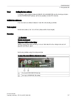
Page 37: ...u can set a bus address between 0 and 99 on the heating controller Tools required Slotted screwdriver size 0 4 x 2 5 mm blade width x blade length Procedure WARNING Electric shock hazard May cause death or serious injury Before opening the enclosure door you must disconnect the line voltage and secure it against switching on again Set the bus address using the rotary switches Location of the rotar...

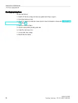
Page 38: ...ge 37 The DP master is configured and in operation Procedure 1 Switch the 24 V DC power supply on again 2 The device starts up Check the LED status for the operating state Error free power up Green LED is on red LED is off This LED display means System is active PROFIBUS communication is taking place 1 Close the enclosure door 2 Switch on the line voltage The device is in operation Note When power...

Page 39: ...lf waves For each half wave the controller supplies On Off information to the relay and this switches as specified at the next zero point The setpoints for controlling the power outputs lie within a value range of 0 to 99 reference value 100 half waves Depending on the specified setpoint the power outputs are controlled with an equal number of positive and negative half waves reference value 200 h...

Page 40: ...tage is connected regardless of heating status all other faults are only indicated when heating is enabled heating is ON Diagnostic functions The faults that can be detected are listed in the table below complete with their error codes Fault Error code Description Special characteristics Heating element fault 1 SSR breakdown 2 Breakdown means the SSR solid state relay is defective and conducts con...

Page 41: ...g will be generated see section Diagnostics data Page 47 and heater operation continues It is the responsibility of the user to respond Note Due to the measuring principle the voltage measuring range lies between 320 V and 480 V Voltages below this are indicated as 0 V Voltages above this are indicated as the full scale value The full scale value can vary between devices by a tolerance of 1 If the...

Page 42: ... and the fine tuning of the control that results from the half wave controller This can be up to 2 8 5 Frequency monitoring Frequency monitoring The frequency of the applied line voltage is continuously monitored If the frequency lies between the permissible limits it is evaluated as valid and reported to the user see section Diagnostics data A distinction is made between the following frequencies...

Page 43: ...y be controlled again when the temperature has returned to the valid range The following data or states are reported to the user Current temperature measured value see section Cyclic input data Page 45 Disconnection due to excessively high temperature see section Diagnostics data Page 47 Heat distribution by means of internal fan To achieve even heat distribution within the enclosure an internal f...

Page 44: ...Functions 8 6 Temperature monitoring SIPLUS HCS3200 44 Operating Instructions 07 2014 A5E31278506C 002 ...

Page 45: ...l modules All addresses are specified as an offset relative to the base address 0 0 The actual addresses are obtained from the configuration of the overall system Table 9 1 Addressing of inputs Byte Bit Meaning Description 0 0 0 Heating switched off 1 Heating switched on Refer to section Power output control Page 39 1 0 Line voltage compensation is not active 1 Line voltage compensation is active ...

Page 46: ...l addresses are obtained from the configuration of the overall system Table 9 2 Addressing of outputs Byte Bit Meaning Description 0 0 0 Heating Off 1 Heating On Refer to section Power output control Page 39 1 0 Line voltage compensation Off 1 Line voltage compensation On Refer to section Line voltage compen sation Page 42 2 7 0 reserved 1 Power output 1 setpoint Refer to section Power output cont...

Page 47: ...r ing Page 42 3 0 Line voltage OK 1 Line voltage outside the working range Refer to section Line supply voltage monitoring Page 41 4 0 Line voltage OK 1 Line voltage outside the measuring range 5 7 0 reserved 11 Frequency 50 60 0 not recognized Refer to section Frequency monitor ing Page 42 12 Error information for power output 1 error code 1 4 Refer to section Power output diag nostics Page 40 13...

Page 48: ...A5E31278506C 002 In the case of the following messages the diagnosis is Fault i e a fault exists that must be rectified Temperature trip threshold reached Line voltage outside the measuring range All power output faults error code 1 4 All other signals are transmitted as status signals ...

Page 49: ... of operating states faults Green LED Red LED Meaning On On System startup this status is only active for a short period of time after connecting the supply voltage Off Off System initialization Off On System is active PROFIBUS communication is not taking place Possible causes CPU has been stopped No connection Incorrect address On Off System is active PROFIBUS communication is active On On During...

Page 50: ...on Switch off machine check fuse cabling heating element and rectify fault restart Outgoing fuse tripped or SSR has high resistance error code 4 Corrective action Switch off machine check fuse cabling heating element and rectify fault restart Solid state relay SSR is defective Return device Overtemperature Possible causes corrective action Temperature in housing 70 C If an excessively high tempera...

Page 51: ...ntervals to guarantee smooth operation of the device Maintenance work Heat sink Check regularly that the cooling ducts on the rear of the device are free from coarse soiling If dirt is visible clean the cooling channels with a vacuum cleaner Internal fan Check regularly that the internal fan is functional Remove dust deposits with a cleaning brush and vacuum cleaner ...

Page 52: ... The HCS3200 is delivered as standard with the current firmware version and is ready to switch on The steps described below only have to be performed if the HCS3200 is to be updated with a different firmware version Prerequisite for loading the firmware You need a null modem cable 9 pin for loading the firmware If you do not have such a cable a cable with the following pin assignment is sufficient...

Page 53: ...face which is used on the PC COM1 or COM2 6 Switch on the 24 V DC supply for the HCS3200 7 All the remaining steps are carried out automatically You can follow the progress of the loading process on the PC The green and red LEDs of the HCS are continuously lit during the loading process the green LED also flashes rapidly for short periods 8 Disconnect the connecting cable from the PC 9 Close the e...

Page 54: ...ards May cause death or serious injury Before changing a fuse you must isolate the load circuit from the supply Before working on the heating control system or the connected components ensure the system is disconnected NOTICE Use only the prescribed fuse types see section Ordering data Page 68 If you operate the device with unapproved fuses the device could be destroyed ...

Page 55: ...fuses The figure below shows the position of the fuses in the enclosure of the heating control system Upper fuse block for fuses F101 to F109 along the incoming lines for heating elements 1 to 9 Lower fuse block for fuses F111 to F119 along the incoming lines for heating elements 1 to 9 Figure 11 1 HCS3200 Position of the fuses ...

Page 56: ...ollows 1 Switch off the line voltage and secure against switching on again 2 Open the enclosure door 3 Check for ruptured or defective fuses refer to fault information in the section Diagnostics data Page 47 4 Replace defective fuses 5 Check corresponding heating elements 6 Close the enclosure door 7 Connect the line voltage 8 Reactivate the device ...

Page 57: ... be disconnected and secured against switching on again before opening the enclosure door NOTICE You must install a fan of the same type in the device You will find a replacement fan in section Ordering data Page 68 Preparations 1 Switch off the line voltage and secure against switching on again 2 Switch off the 24 V DC power supply of the HCS3200 3 Open the enclosure door Tool You will need a 2 5...

Page 58: ...oceed as follows to remove the fan Steps 1 Open the 3 plug in terminals using a screwdriver as a lever and detach the fan leads Terminal closed Terminal open 2 The internal fan of the HCS3200 is fixed without screws Rotate the fan unit in the clockwise direction as far as the stop and then remove it Fan fixed in place Fan released ...

Page 59: ...er clamp 2 Insert the mushroom shaped feet of the fan unit into the larger fastening holes Rotate fan unit counterclockwise into the smaller holes Position of the mounting holes 3 The picture shows the correct fan mounting position Note the direction of the arrow shown on the fan Fan installed and connected 4 Insert the fan leads into the 3 insulation displacement terminals Lock the leads in place...

Page 60: ...ce see section Mounting the device Page 22 Installing and connecting the new device Installation steps 1 Install the replacement device see section Mounting the device Page 22 2 Reconnect all plugs to the replacement device see section Connection element locations Page 27 Commissioning the new inverter Steps for commissioning 1 Set the correct bus address see section Setting the bus address Page 3...

Page 61: ...tters Half wave control Type of load Ohmic load Verification of suitability CE UL Degree of pollution 2 Main circuit Power load capacity maximum permissible kW 25 2 Switching capacity current per phase maximum A 63 Type of voltage of supply voltage AC Supply voltage for AC rated value V 400 Supply voltage frequency 1 rated value Hz 50 2 rated value Hz 60 Relative symmetrical tolerance of the suppl...

Page 62: ...ting power per output Fuse 15 A Design of the electrical isolation Optocoupler between main circuit and PELV Galvanic isolation between the outputs No Communications Protocol is supported PROFIBUS DP protocol Yes Transfer rate for PROFIBUS DP maximum Mbit s 12 Display Number of status displays 2 Type of display as status display by LED LED green status indicator LED red fault indicator Supply volt...

Page 63: ...ctions for heating and fan finely stranded with end sleeve 18x 1 5 4 mm 1x PE 1 5 16 mm for AWG conductors stranded 18x 18 12 Monitoring functions Type of the temperature monitoring NTC thermistor Mechanical features mounting position vertical Type of mounting screw fixing Nature of the ventilation Self ventilation Resistance against shock according to IEC 60068 2 27 15g 11 ms 3 shocks axis Vibrat...

Page 64: ... according to IEC 61000 4 6 10 V 0 15 80 MHz Electrostatic discharge according to IEC 61000 4 2 4 kV contact discharge 8 kV air dis charge Field bound parasitic coupling according to IEC 61000 4 3 10 V m 80 MHz 1000 MHz 3 V m 1 4 GHz 2 0 GHz 1 V m 2 0 GHz 2 7 GHz EMC emitted interference in accordance with IEC 61000 6 4 2007 A1 2011 Overvoltage class III Ambient climatic conditions Ambient tempera...

Page 65: ...Technical data 12 2 Dimension drawings SIPLUS HCS3200 Operating Instructions 07 2014 A5E31278506C 002 65 12 2 Dimension drawings Figure 12 1 SIPLUS HCS3200 dimension drawing ...

Page 66: ...Technical data 12 2 Dimension drawings SIPLUS HCS3200 66 Operating Instructions 07 2014 A5E31278506C 002 ...

Page 67: ...tive SIPLUS HCS3200 products meet the requirement of the EC Directive 2006 95 EC Electrical Safety The product is designed in accordance with EN 61010 1 EMC directive electromagnetic compatibility SIPLUS HCS3200 products meet the requirements of the EC Directive 2004 108 EC Electromagnetic Compatibility The product is designed for operation in industrial areas with the following requirements Inter...

Page 68: ...parts accessories A 2 1 Ordering data Ordering data Single part Order number HCS3200 device UL variant 6BK1932 0AA00 0AA0 Spare fuse for heat emitter connection F101 F109 F111 F119 Cylindrical fuse Class CC 10x38 15A Manufacturer Siemens Order No 3NW6005 1 Manufacturer Cooper Bussmann www cooperindustries com Order No C10G16 Internal fan 6BK1932 6AA00 0AA0 Double bit key for 3 mm lug 8GD9290 Wall ...

Page 69: ... homepage www siemens com automation service support of IA DT on the Internet There you will find the following information for example Our newsletter containing up to date information on your products Relevant documentation for your application which you can access via the search function in Product Support A forum for global information exchange by users and specialists Your local contact for IA...

Page 70: ...Application example Application example An example application for S7 and SIMOTION is available as a guide and basis for your own applications This application example explains the mode of operation of the heater control You can download the application example from the Siemens Service Support website ...

Page 71: ...es 9 Connection elements 27 Location 27 Connectors Location 27 Control Heating elements 39 Controller 15 Cooling fins 21 Cyclic data 45 Cyclic input data 45 Cyclic output data 46 D Damage during transportation 17 Diagnostics 13 Diagnostics data 47 50 Diagnostics function 40 Power output fault 40 40 Disconnecting means 18 Display Fault 49 Operating states 49 Disposal 60 Distributed I O 15 DP master...

Page 72: ...oltage monitoring 41 Line voltage compensation 13 42 Low voltage directive 67 M Mains connection Connectors 28 Pin assignment 28 Manufacturer s warranty 9 Monitoring functions 50 Mounting 21 horizontal 22 Mounting bracket 22 vertical 22 Mounting bracket 22 N Non Siemens DP master 35 O OB82 47 Operating state 38 Ordering data 68 Outgoing fuse 40 Overtemperature 50 P PII 45 PIQ 46 Power output Fault...

Page 73: ... 9 Fuse replacement 10 Repairs 10 Shipping 17 Working on the device 10 Scope of delivery 17 Serial interface 13 SFC13 47 Shipping 17 SIMATIC S7 controller 15 SIMOTION 15 Solid state relay 39 SSR 40 STEP 7 35 Structure 14 System components 15 System configuration 15 System initialization 49 System startup 49 T Target group 7 Technical Support 69 Temperature measured value 43 Temperature monitoring ...

Page 74: ......
Reviews: