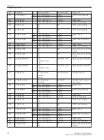


Setting Notes
General
The circuit-breaker failure protection and its ancillary functions (end fault protection, pole discrepancy supervi-
sion) can only operate if they were set during configuration of the scope of functions (address 139
50BF
,
setting
Enabled
or
enabled w/ 3I0>
).
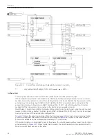
Breaker Failure Protection (50BF)
The breaker failure protection is switched
ON
or
OFF
at address 3901
FCT 50BF Break.
.
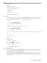
The current threshold
50BF PICKUP
(address 3902) should be selected such that the protection will operate
with the smallest expected fault current. A setting of 10 % below the minimum fault current for which breaker
failure protection must operate is recommended. On the other hand, the value should not be set lower than
necessary
If the breaker failure protection is configured with zero sequence current threshold (address 139 =
enabled
w/ 3I0>
), the pickup threshold for the zero sequence current
50NBF PICKUP
(address 3912) can be set
independently of
50BF PICKUP
.
Normally, the breaker failure protection evaluates the current flow criterion as well as the position of the
breaker auxiliary contact(s). If the auxiliary contact(s) status is not available in the device, this criterion cannot
be processed. In this case, set address 3909
Chk BRK CONTACT
to
NO
.
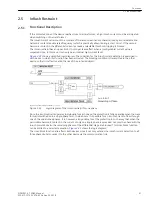
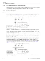
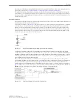
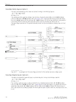
Two-Element Breaker Failure Protection
With two-element operation, the trip command is repeated after a time delay T1 to the local feeder breaker,
normally to a different set of trip coils of this breaker.
If the circuit breaker does not respond to this trip repetition, the adjacent circuit breakers are tripped after T2,
i.e. the circuit breakers of the busbar or of the concerned busbar section and, if necessary, also the circuit
breaker at the remote end unless the fault has been cleared.
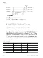
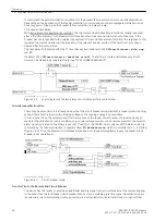
The time delays can be set separately
•
for trip repetition to the local feeder circuit breaker after a trip of the feeder protection
50BF-1 Delay
3p
(address 3905),
•
for trip of the adjacent circuit breakers (busbar zone and remote end if applicable)
50BF-2 Delay
at
address 3906.
The time delays to be set should be based on the maximum circuit-breaker operating time plus the dropout
time of the current flow monitoring element plus a safety margin which takes into consideration the tolerance
of the time delay.
illustrates the time sequences in an example. The dropout time for sinusoidal
currents is ≤ 15 ms. If current transformer saturation is anticipated, the time should be set to 25 ms.
i
i
NOTE
To prevent automatic reclosing after
50BF BusTrip
, you can set the time 3408
T-Start MONITOR
so
that it elapses together with
50BF-2 Delay
y.
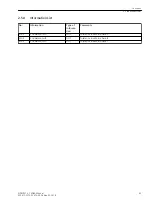
2.6.2
Functions
2.6 Circuit Breaker Failure Protection 50BF
100
SIPROTEC 4, 7SD80, Manual
E50417-G1100-C474-A2, Edition 02.2018
Summary of Contents for SIPROTEC 4 7SD80
Page 8: ...8 SIPROTEC 4 7SD80 Manual E50417 G1100 C474 A2 Edition 02 2018 ...
Page 10: ...10 SIPROTEC 4 7SD80 Manual E50417 G1100 C474 A2 Edition 02 2018 ...
Page 18: ...18 SIPROTEC 4 7SD80 Manual E50417 G1100 C474 A2 Edition 02 2018 ...
Page 248: ...248 SIPROTEC 4 7SD80 Manual E50417 G1100 C474 A2 Edition 02 2018 ...
Page 298: ...298 SIPROTEC 4 7SD80 Manual E50417 G1100 C474 A2 Edition 02 2018 ...
Page 312: ...312 SIPROTEC 4 7SD80 Manual E50417 G1100 C474 A2 Edition 02 2018 ...
Page 322: ...322 SIPROTEC 4 7SD80 Manual E50417 G1100 C474 A2 Edition 02 2018 ...
Page 400: ...400 SIPROTEC 4 7SD80 Manual E50417 G1100 C474 A2 Edition 02 2018 ...
Page 402: ...402 SIPROTEC 4 7SD80 Manual E50417 G1100 C474 A2 Edition 02 2018 ...


