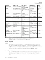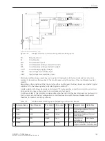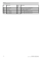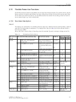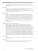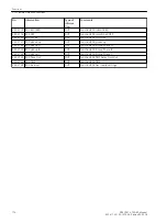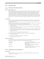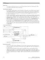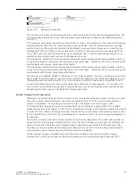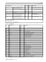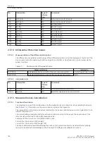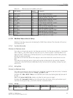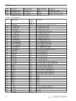
Parameter
OPERRAT. MODE
=
1-phase
Va-n
Vb-n
Vc-n
Va-b
Vb-c
Vc-a
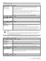
It is determined which voltage-measuring channel must be evaluated by the function.
When selecting phase-to-phase voltage, the threshold value must be set as a phase-to-
phase value, when selecting a phase-to-ground variable as phase-to-ground voltage.
Parameter
MEAS. QUANTITY
=
P forward
or
P reverse
or
Q forward
or
Q reverse
Parameter
POWER
Ia Va-n
Ib Vb-n
Ic Vc-n
It is determined which power-measuring channel (current and voltage) must be evaluated
by the function.
The forward direction of the power (P forward, Q reverse) is in direction of the line. The parameter (1107
P,Q
sign
) for sign reversal of the power indication in the operational measured values is ignored by the flexible
functions.
Parameter
PICKUP WITH
can be used to specify whether the function is to pick up when the set threshold
value is exceeded or undershot.
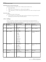
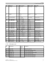
Settings
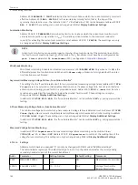
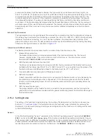
The pickup thresholds, time delays and dropout ratios of the flexible protection function are set in the
“Settings” dialog box in DIGSI.
The pickup threshold of the function is configured via parameter
P.U. THRESHOLD
. The OFF-command time
delay is set via parameter
T TRIP DELAY
. Both setting values must be selected according to the required
application.
The pickup can be delayed via parameter
T PICKUP DELAY
. For protection applications this parameter is
usually set to zero (default setting), because a protection function must pick up as quickly as possible. A
setting other than zero can be useful if it is not desired that a fault record is opened each time a pickup
threshold is briefly exceeded, e.g. for the power protection or if the function is used as monitoring function
and not as protection function. If the ratio of the positive-sequence current to the negative-sequence current
(I2/I1) is evaluated, the
T PICKUP DELAY
should at least be set to 20 ms.
When setting the power threshold values, it is important to take into consideration that a minimum current of
0.03
Ι
N
is required for power calculation. The power calculation is blocked for lower currents.
The dropout of pickup can be delayed via parameter
T DROPOUT DELAY
. This setting is also set to zero by
default (standard setting) A setting deviating from zero may be required if the device is utilized together with
electro-magnetic devices with considerably longer dropout ratios than the digital protection device (see
Chapter “Phase Comparison Protection and Ground Differential Protection” for more information). When
utilizing the dropout time delay, it is recommended to set it to a shorter time than the OFF-command time
delay in order to avoid both times to “race”.
Parameter
BLK.by Vol.Loss
determines whether a function whose measured variable is based on a voltage
measurement (measured quantities voltage, P forward, P reverse, Q forward, Q reverse and power factor),
should be blocked in case of a measured voltage failure (set to
YES
) or not (set to
NO
).
The dropout ratio of the function can be selected in parameter
DROPOUT RATIO
. The standard dropout ratio
of protection functions is 0.95 (default setting). If the function is used as power protection, a dropout ratio of
at least 0.9 should be set. The same applies to the utilization of the symmetrical components of current and
voltage. If the dropout ratio is decreased, it would be sensible to test the pickup of the function regarding
possible “chatter”.
The dropout difference of the frequency elements is set under parameter
DO differential
. Usually, the
default setting of 0.02 Hz can be retained. A higher dropout difference should be set in weak systems with
larger, short-term frequency fluctuations to avoid chattering of the message.
A permanent dropout difference of 0.1 Hz/s is used for the frequency change (df/dt) measurand. The same
applies to the voltage change (dU/dt) measurand. The permanent dropout difference here is 3 V/s.
Functions
2.15 Flexible Protection Functions
SIPROTEC 4, 7SD80, Manual
173
E50417-G1100-C474-A2, Edition 02.2018
Summary of Contents for SIPROTEC 4 7SD80
Page 8: ...8 SIPROTEC 4 7SD80 Manual E50417 G1100 C474 A2 Edition 02 2018 ...
Page 10: ...10 SIPROTEC 4 7SD80 Manual E50417 G1100 C474 A2 Edition 02 2018 ...
Page 18: ...18 SIPROTEC 4 7SD80 Manual E50417 G1100 C474 A2 Edition 02 2018 ...
Page 248: ...248 SIPROTEC 4 7SD80 Manual E50417 G1100 C474 A2 Edition 02 2018 ...
Page 298: ...298 SIPROTEC 4 7SD80 Manual E50417 G1100 C474 A2 Edition 02 2018 ...
Page 312: ...312 SIPROTEC 4 7SD80 Manual E50417 G1100 C474 A2 Edition 02 2018 ...
Page 322: ...322 SIPROTEC 4 7SD80 Manual E50417 G1100 C474 A2 Edition 02 2018 ...
Page 400: ...400 SIPROTEC 4 7SD80 Manual E50417 G1100 C474 A2 Edition 02 2018 ...
Page 402: ...402 SIPROTEC 4 7SD80 Manual E50417 G1100 C474 A2 Edition 02 2018 ...

