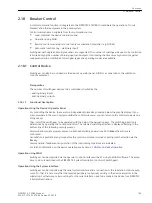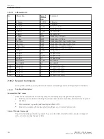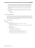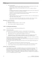
Breaker Control
A control command function is integrated in the SIPROTEC 4 7SD80 to coordinate the operation of circuit
breakers and other equipment in the power system.
Control commands can originate from four command sources:
•
Local control at the device's operator panel
•
Operation using DIGSI
•
Remote control via network control center or substation controller (e.g. SICAM)
•
Automatic functions (e.g., via binary input)
Switchgear with single and multiple busbars are supported. The number of switchgear devices to be controlled
is limited only by the number of binary inputs and outputs. Interlocking checks ensure high security against
maloperation and a multitude of switchgear types and operating modes are available.
Control Device
Switchgear can also be controlled via the device's operator panel, DIGSI or a connection to the substation
control equipment.
Prerequisites
The number of switchgear devices to be controlled is limited by the
– existing binary inputs
– existing binary outputs
Functional Description
Operation Using the Device's Operator Panel
For controlling the device, there are two independent colored keys located below the graphic display. If you
are somewhere in the menu system outside the control submenu, you can return to the control mode via one
of these keys.
Then, select the switchgear to be operated with the help of the navigation keys. The switching direction is
determined by operating the I or O pushbutton. The selected switching direction is displayed flashing in the
bottom line of the following security prompt.
Password and security prompts prevent unintended switching operations. With Enter the entries are
confirmed.
Cancellation is possible at any time before the control command is issued or during switch selection via the
Esc key.
Command end, feedback or any violation of the interlocking conditions are indicated.
For further information on the device operation see Section
2.19 Notes on Device Operation
Operation using DIGSI
Switchgear can be controlled via the operator control interface with a PC using the DIGSI software. The proce-
dure to do so is described in the SIPROTEC 4 System Description (Control of Switchgear).
Operation Using the System Interface
Switchgear can be controlled via the serial system interface and a connection to the substation control equip-
ment. For that it is necessary that the required periphery is physically existing in the device as well as in the
substation. Furthermore, certain settings for the serial interface need to be made in the device (see SIPROTEC
4 System Description).
2.18
2.18.1
2.18.1.1
Functions
2.18 Breaker Control
SIPROTEC 4, 7SD80, Manual
193
E50417-G1100-C474-A2, Edition 02.2018
Summary of Contents for SIPROTEC 4 7SD80
Page 8: ...8 SIPROTEC 4 7SD80 Manual E50417 G1100 C474 A2 Edition 02 2018 ...
Page 10: ...10 SIPROTEC 4 7SD80 Manual E50417 G1100 C474 A2 Edition 02 2018 ...
Page 18: ...18 SIPROTEC 4 7SD80 Manual E50417 G1100 C474 A2 Edition 02 2018 ...
Page 248: ...248 SIPROTEC 4 7SD80 Manual E50417 G1100 C474 A2 Edition 02 2018 ...
Page 298: ...298 SIPROTEC 4 7SD80 Manual E50417 G1100 C474 A2 Edition 02 2018 ...
Page 312: ...312 SIPROTEC 4 7SD80 Manual E50417 G1100 C474 A2 Edition 02 2018 ...
Page 322: ...322 SIPROTEC 4 7SD80 Manual E50417 G1100 C474 A2 Edition 02 2018 ...
Page 400: ...400 SIPROTEC 4 7SD80 Manual E50417 G1100 C474 A2 Edition 02 2018 ...
Page 402: ...402 SIPROTEC 4 7SD80 Manual E50417 G1100 C474 A2 Edition 02 2018 ...

