
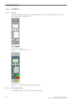


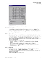


Changing the Operating State
When clicking one of the buttons in the column Action for the first time, you will be prompted for the pass-
word no. 6 (for hardware test menus). After correct entry of the password, individual annunciations can be
initiated. To do so, click on the button Send on the corresponding line. The corresponding message is issued
and can be read out either from the event log of the SIPROTEC 4 device or from the substation control system.
As long as the window is open, further tests can be performed.
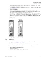
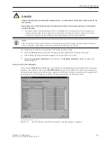
Test in Message Direction
For all information that is transmitted to the central station, test the options in the list which appears in
SETPOINT Status:
•
Make sure that each checking process is carried out carefully without causing any danger (see above and
refer to DANGER!)
•
Click on Send in the function to be tested and check whether the transmitted information reaches the
central station and shows the desired reaction. Data which are normally linked via binary inputs (first
character “>”) are likewise indicated to the central power system with this procedure. The function of the
binary inputs itself is tested separately.
Exiting the Test Mode
To end the System Interface Test, click on Close. The device is briefly out of service while the start-up routine
is executed. The dialog box closes.
Test in Command Direction
The information transmitted in command direction must be indicated by the central station. Check whether
the reaction is correct.
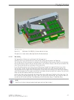
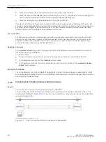
Configuring Communication Modules
Required Settings in DIGSI 4
The following applies in general:
In the case of a first-time installation or replacement of a communication module, the ordering number
(MLFB) does not need to be changed. The ordering number can be retained. Thus, all previously created
parameter sets remain valid for the device.
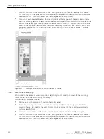
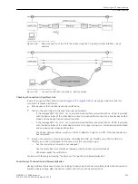
Changes in DIGSI Manager
For the protection device to be able to access the new communication module, a change has to be made in
the parameter set in DIGSI Manager.
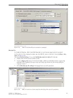
In DIGSI 4 Manager, select the SIPROTEC device in your project and select the menu item Edit > Object Prop-
erties to open the Properties – SIPROTEC 4 Device dialog box (see following Figure).
In the Communication modules tab, select an interface for the 11. Port B (bottom side of device) using the
pull-down button. Select Additional Protocols, see MLFB Ext. for Profibus DP, Modbus or DNP3.0.
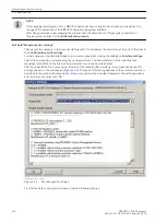
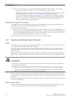
The type of communication module for port B can be specified in the Additional Information dialog box using
the button L.: ....
3.3.4
Mounting and Commissioning
3.3 Commissioning
230
SIPROTEC 4, 7SD80, Manual
E50417-G1100-C474-A2, Edition 02.2018
Summary of Contents for SIPROTEC 4 7SD80
Page 8: ...8 SIPROTEC 4 7SD80 Manual E50417 G1100 C474 A2 Edition 02 2018 ...
Page 10: ...10 SIPROTEC 4 7SD80 Manual E50417 G1100 C474 A2 Edition 02 2018 ...
Page 18: ...18 SIPROTEC 4 7SD80 Manual E50417 G1100 C474 A2 Edition 02 2018 ...
Page 248: ...248 SIPROTEC 4 7SD80 Manual E50417 G1100 C474 A2 Edition 02 2018 ...
Page 298: ...298 SIPROTEC 4 7SD80 Manual E50417 G1100 C474 A2 Edition 02 2018 ...
Page 312: ...312 SIPROTEC 4 7SD80 Manual E50417 G1100 C474 A2 Edition 02 2018 ...
Page 322: ...322 SIPROTEC 4 7SD80 Manual E50417 G1100 C474 A2 Edition 02 2018 ...
Page 400: ...400 SIPROTEC 4 7SD80 Manual E50417 G1100 C474 A2 Edition 02 2018 ...
Page 402: ...402 SIPROTEC 4 7SD80 Manual E50417 G1100 C474 A2 Edition 02 2018 ...


