


Final Preparation of the Device
Firmly tighten all screws. Tighten all terminal screws, including those that are not used.
!
CAUTION
Inadmissible Tightening Torques!
The tightening torques must not be exceeded as the threads and terminal chambers may otherwise
be damaged!
²
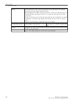
The setting values should be checked again, if they were modified during the tests. Check if protection,
control and auxiliary functions to be found with the configuration parameters are set correctly (Section
, Functional Scope). All desired elements and functions must be set
ON
. Ensure that a
copy of the setting values is stored on the PC.
The user should check the device-internal clock and set/synchronize it if necessary, provided that it is not
synchronized automatically. Refer to the SIPROTEC 4 System Description for more information on this.
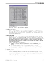
The indication buffers are deleted under Main Menu → Annunciation →
Set/Reset
, so that in the future
they only contain information on actual events and states. The counters in the switching statistics should be
reset to the values that were existing prior to the testing (see also SIPROTEC 4 System Description).
The counters of the operational measured values (e.g. operation counter, if available) are reset under Main
Menu → Measurement →
Reset
(see also SIPROTEC 4 System Description).
Press the ESC key, several times if necessary, to return to the default display. The default display appears in
the display (e.g. display of operational measured values).
Clear the LEDs on the front panel by pressing the LED key, so that they only show real events and states. In
this context, saved output relays are reset, too. Pressing the LED key also serves as a test for the LEDs on the
front panel because they should all light when the button is pushed. If the LEDs display states relevant by that
moment, these LEDs, of course, stay lit.
The green “RUN” LED must light up, whereas the red “ERROR” must not light up.
Close the protective switches. If test switches are available, then these must be in the operating position.
The device is now ready for operation.
3.4
Mounting and Commissioning
3.4 Final Preparation of the Device
SIPROTEC 4, 7SD80, Manual
247
E50417-G1100-C474-A2, Edition 02.2018
Summary of Contents for SIPROTEC 4 7SD80
Page 8: ...8 SIPROTEC 4 7SD80 Manual E50417 G1100 C474 A2 Edition 02 2018 ...
Page 10: ...10 SIPROTEC 4 7SD80 Manual E50417 G1100 C474 A2 Edition 02 2018 ...
Page 18: ...18 SIPROTEC 4 7SD80 Manual E50417 G1100 C474 A2 Edition 02 2018 ...
Page 248: ...248 SIPROTEC 4 7SD80 Manual E50417 G1100 C474 A2 Edition 02 2018 ...
Page 298: ...298 SIPROTEC 4 7SD80 Manual E50417 G1100 C474 A2 Edition 02 2018 ...
Page 312: ...312 SIPROTEC 4 7SD80 Manual E50417 G1100 C474 A2 Edition 02 2018 ...
Page 322: ...322 SIPROTEC 4 7SD80 Manual E50417 G1100 C474 A2 Edition 02 2018 ...
Page 400: ...400 SIPROTEC 4 7SD80 Manual E50417 G1100 C474 A2 Edition 02 2018 ...
Page 402: ...402 SIPROTEC 4 7SD80 Manual E50417 G1100 C474 A2 Edition 02 2018 ...


