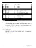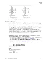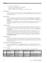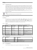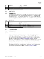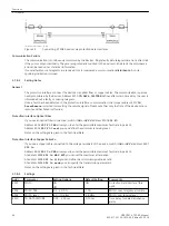
ANSI characteristic (
50(N) 51(N)ANSI
). This selection is independent of whether the time overcurrent
protection is intended to operate as emergency protection (only in case of protection communication failure)
or as independent backup protection. Device versions equipped with directional overcurrent protection (MLFB
position 14 = R or S) additionally provide a directional definite time overcurrent protection element and a
directional inverse time overcurrent protection element. The characteristic curves of the two inverse time
overcurrent protection elements are identical. The different characteristic curves are shown in the Technical
Data (Section
4.7 Time Overcurrent Protection
). You can also disable the time overcurrent protection (
Disa-
bled
).
Set to
Disabled
, the entire time overcurrent protection can be disabled.
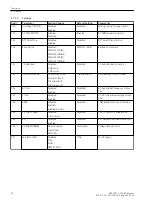
For overload protection you can define in address 142
49
whether the function is to be
Enabled
or
Disa-
bled
.
In address 139 you can set the breaker failure protection to
Enabled
or
Disabled
. The setting option
enabled w/ 3I0>
subjects the ground current and the negative sequence current to a plausibility check.
If the device features an automatic reclosing function, address 133 and 134 are of importance. Automatic
reclosure is only permitted for overhead lines. It must not be used in any other case. If the protected object
consists of a combination of overhead lines and other equipment (e.g. overhead line/cable), reclosing is only
permissible if it is ensured that reclosing will only be performed in the event of a fault on the overhead line. If
no automatic reclosing function is desired for the feeder at which 7SD80 operates, or if an external device is
used for reclosure, set address 133
79 Auto Recl.
to
Disabled
. Or you can enter the number of desired
reclosing attempts there. You can select
1 AR-cycle
or
2 AR-cycles
.
The
AR control mode
at address 134 allows a maximum of four options. On the one hand, it can be deter-
mined whether the automatic reclosure cycles are carried out according to the fault type detected by the
pickup of the starting protective function(s) or according to the type of trip command. On the other hand,
the automatic reclosing function can be operated with or without action time.
The setting
Trip ...
(with trip command ..., default setting) allows you to specify different dead times for
each automatic reclose cycle.
The setting
Pickup ...
(with pickup ...) allows you to enter different dead times for the automatic reclose
cycles for 1-phase, 2-phase and 3-phase short circuits. The pickup status of the protection functions at the
instant the trip command disappears is decisive here. This operating mode enables making the dead times
dependent on the type of fault also for three-pole reclosure cycles. Tripping is always 3-pole.
The setting
... w/ Tact
(with ... action time) provides an action time for each automatic reclose cycle. The
action time is started by a general pickup of all protection functions. If there is no trip command yet when the
action time has expired, the corresponding automatic reclosure cycle cannot be executed. Section 2.11
provides detailed information on this topic. For time graded protection this setting is recommended. If the
protection function which is to operate with automatic reclosure does not have a general pickup signal for
starting the action times, select ... w/o Tact (without action time).
Address 137
27/59
allows activating the voltage protection function with a variety of undervoltage and over-
voltage protection elements.
For the trip circuit supervision enter the number of trip circuits to be monitored at address 140
74 Trip Ct
Supv
1 trip circuit
,
2 trip circuits
or
3 trip circuits
, unless you omit it (
Disabled
).
If the device is connected to voltage transformers, specify this condition in address 144
V-TRANSFORMER
. The
voltage-based functions, for instance the directional overcurrent protection elements, the ground fault differ-
ential protection in resonant-grounded/isolated systems or determination of the voltage-based measured
values, can only be activated if voltage transformers are connected.
The flexible protection functions can be configured via parameter
FLEXIBLE FUNC.
. You can create up to 20
flexible functions by setting a checkmark in front of the desired function. If the checkmark of a function is
removed, all settings and configurations made previously will be lost. After re-selecting the function, all
settings and configurations are in default setting. The flexible function can be configured in DIGSI at
“Settings”, “Additional Functions” and “Settings”. The routing is done, as usual, under “Settings” and “Masking
I/O”. If you want to use the flexible protection function, the device must be connected to voltage transformers.
Functions
2.1 General
SIPROTEC 4, 7SD80, Manual
31
E50417-G1100-C474-A2, Edition 02.2018
Summary of Contents for SIPROTEC 4 7SD80
Page 8: ...8 SIPROTEC 4 7SD80 Manual E50417 G1100 C474 A2 Edition 02 2018 ...
Page 10: ...10 SIPROTEC 4 7SD80 Manual E50417 G1100 C474 A2 Edition 02 2018 ...
Page 18: ...18 SIPROTEC 4 7SD80 Manual E50417 G1100 C474 A2 Edition 02 2018 ...
Page 248: ...248 SIPROTEC 4 7SD80 Manual E50417 G1100 C474 A2 Edition 02 2018 ...
Page 298: ...298 SIPROTEC 4 7SD80 Manual E50417 G1100 C474 A2 Edition 02 2018 ...
Page 312: ...312 SIPROTEC 4 7SD80 Manual E50417 G1100 C474 A2 Edition 02 2018 ...
Page 322: ...322 SIPROTEC 4 7SD80 Manual E50417 G1100 C474 A2 Edition 02 2018 ...
Page 400: ...400 SIPROTEC 4 7SD80 Manual E50417 G1100 C474 A2 Edition 02 2018 ...
Page 402: ...402 SIPROTEC 4 7SD80 Manual E50417 G1100 C474 A2 Edition 02 2018 ...

