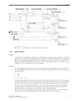
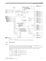


Setting Notes
General
The voltage protection can only operate if it has been set to
Enabled
during the configuration of the device
scope (address 137).
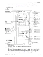
The overvoltage and undervoltage elements can detect phase-to-ground voltages, phase-to-phase voltages or
the symmetrical positive sequence system of the voltages; the symmetrical negative sequence system or the
zero sequence voltage can also be used for overvoltage. Any combination is possible. Detection procedures
that are not required are switched
OFF
.
i
i
NOTE
For overvoltage protection it is particularly important to observe the setting notes: Never set an over-
voltage element (V
L-N
, V
L-L
, V
1
) lower than an undervoltage element. This would put the device immediately
into a state of permanent pickup which cannot be reset by any measured value operation. As a result, oper-
ation of the device would be impossible!
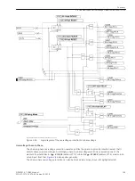
Overvoltage Phase-to-Ground
The phase voltage elements can be switched
ON
or
OFF
in address 3701
59-Vph-g Mode
. In addition to this,
you can set
Alarm Only
, i.e. these elements operate and send alarms but do not generate any trip
command. The setting
V>Alarm V>>Trip
creates in addition also a trip command only for the 59-2 element
(V>>).
The settings of the voltage threshold and the timer values depend on the type of application. To detect steady-
state overvoltages on long lines carrying no load, set the
59-1-Vph PICKUP
element (address 3702) to at
least 5 % above the maximum stationary phase-to-ground voltage expected during operation. Additionally, a
high dropout to pickup ratio is required (address 3709
59-Vph RESET
=
0.98
= presetting). This parameter
can only be set in DIGSI at Display Additional Settings. The time delay
59-1-Vph DELAY
(address 3703)
should be a few seconds so that overvoltages with short duration do not cause tripping.
The 52-2 phase (V
ph
>>) element (address 3704) is provided for high overvoltages with short duration. Here an
adequately high pickup value is set, e.g. the 1/
2
-fold of the nominal phase-to-ground voltage. 0.1 s to 0.2 s are
then sufficient for the time delay
59-2-Vph DELAY
(address 3705).
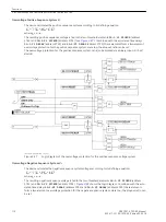
Overvoltage Phase-to-Phase
Basically, the same considerations apply as for the phase undervoltage elements. These elements may be used
instead of the phase voltage elements or be used additionally.. Accordingly set address 3711
59-Vph-ph
Mode
to
ON
,
OFF
,
Alarm Only
or
V>Alarm V>>Trip
.
As phase-to-phase voltages are monitored, the phase–to–phase values are used for the settings
59-1-Vpp
PICKUP
(address 3712) and
59-2-Vpp PICKUP
(address 3714).
For the time delays
59-1-Vpp DELAY
(address 3713) and
59-2-Vpp DELAY
(address 3715) the same
considerations apply as above. The same is true for the dropout ratios (address 3719
59-Vpp RESET
). The
latter setting can only be altered in DIGSI at Display Additional Settings.
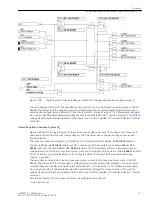
Overvoltage Positive Sequence System V
1
The positive sequence voltage elements can be used instead of or in addition to previously mentioned over-
voltage elements. Accordingly set address 3731
59-V1 Mode
to
ON
,
OFF
,
Alarm Only
or
V>Alarm
V>>Trip
.
For symmetrical voltages an increase of the positive sequence system corresponds to a logical AND combina-
tion of the phase voltages. These elements are particularly suited to the detection of steady-state overvoltages
on long, weak-loaded transmission lines (Ferranti effect). Here too, the
59-1-V1 PICKUP
element (address
3732) with a longer time delay
59-1-V1 DELAY
(address 3733) is used for the detection of steady-state
overvoltages (some seconds), the
59-2-V1 PICKUP
element (address 3734) with the short time delay
59-2-V1 DELAY
(address 3735) is used for the detection of high overvoltages that may jeopardize insula-
tion.
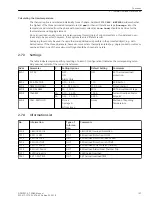
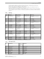
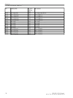
2.8.3
Functions
2.8 Undervoltage and Overvoltage Protection (optional) 27/59
SIPROTEC 4, 7SD80, Manual
115
E50417-G1100-C474-A2, Edition 02.2018
Summary of Contents for SIPROTEC 4 7SD80
Page 8: ...8 SIPROTEC 4 7SD80 Manual E50417 G1100 C474 A2 Edition 02 2018 ...
Page 10: ...10 SIPROTEC 4 7SD80 Manual E50417 G1100 C474 A2 Edition 02 2018 ...
Page 18: ...18 SIPROTEC 4 7SD80 Manual E50417 G1100 C474 A2 Edition 02 2018 ...
Page 248: ...248 SIPROTEC 4 7SD80 Manual E50417 G1100 C474 A2 Edition 02 2018 ...
Page 298: ...298 SIPROTEC 4 7SD80 Manual E50417 G1100 C474 A2 Edition 02 2018 ...
Page 312: ...312 SIPROTEC 4 7SD80 Manual E50417 G1100 C474 A2 Edition 02 2018 ...
Page 322: ...322 SIPROTEC 4 7SD80 Manual E50417 G1100 C474 A2 Edition 02 2018 ...
Page 400: ...400 SIPROTEC 4 7SD80 Manual E50417 G1100 C474 A2 Edition 02 2018 ...
Page 402: ...402 SIPROTEC 4 7SD80 Manual E50417 G1100 C474 A2 Edition 02 2018 ...


