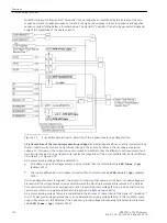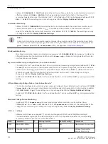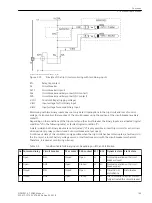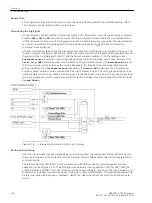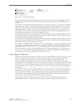
(if the circuit breaker is closed) or through the bypass resistor R. Only as long as the trip contact is closed, the
binary input is faulted and thereby deactivated (logical condition “L”).
If the binary input is permanently deactivated during operation, an interruption in the trip circuit or a failure of
the (trip) control voltage can be assumed.
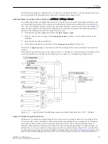
The trip circuit monitor does not operate during system faults. A momentary closed tripping contact does not
lead to a failure message. If however other trip relay contacts from different devices are connected in parallel
in the trip circuit, the failure alarm must be delayed by
Alarm Delay
). After the
fault in the trip circuit is removed, the alarm is reset automatically after the same time.
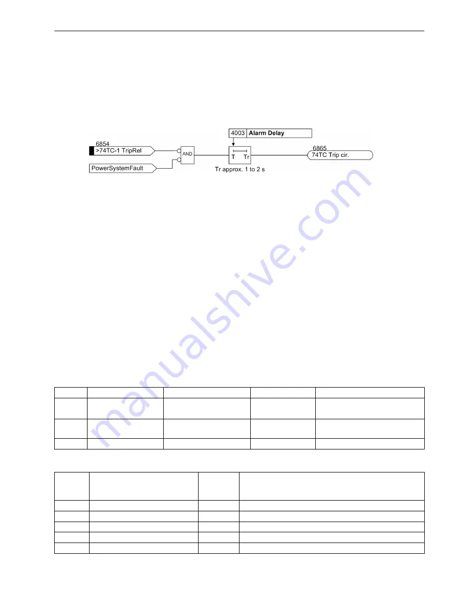
[logikdiagramm-auskruebrwchg-1-be-wlk-310702, 1, en_US]
Figure 2-76
Logic diagram for trip circuit monitoring with one binary input
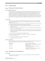
Setting Notes
General
The number of circuits to be monitored was set during the configuration in address 140
74 Trip Ct Supv
). If the trip circuit supervision is not used at all, the setting
Disabled
must be
applied there.
The trip circuit supervision can be switched
ON
or
OFF
in address 4001
FCT 74TC
. The number of binary
inputs that shall be used in each of the monitored circuits is set in address 4002
No. of BI
. If routing of the
required binary inputs does not comply with the selected supervision mode, the alarm
TripCx Prog-
FAIL...
is given (with identification of the non-compliant circuit).
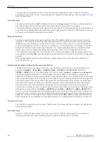
Monitoring with One Binary Input
The alarm for monitoring with two binary inputs is always delayed by approx. 1 s to 2 s, whereas the time
delay of the alarm for monitoring with one binary input can be set in address 4003
Alarm Delay
. 1s to 2s
are sufficient if only the 7SD80 device is connected to the trip circuits as the trip circuit supervision does not
operate during a system fault. If, however, trip contacts from other devices are connected in parallel in the trip
circuit, the alarm must be delayed such that the longest trip command duration can be reliably bridged.
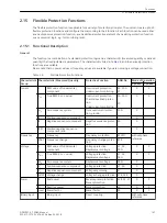
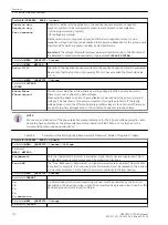
Settings
Addr.
Parameter
Setting Options
Default Setting
Comments
4001
FCT 74TC
ON
OFF
OFF
74TC TRIP Circuit Supervision
4002
No. of BI
1 .. 2
2
Number of Binary Inputs per trip
circuit
4003
Alarm Delay
1 .. 30 sec
2 sec
Delay Time for alarm
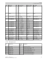
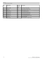
Information List
No.
Information
Type of
Informa-
tion
Comments
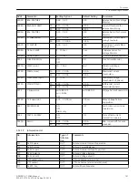
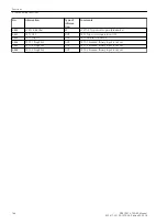
6854
>74TC-1 TripRel
SP
>74TC-1 Trip circuit superv.:Trip Relay
6855
>74TC-1 Bkr.Rel
SP
>74TC-1 Trip circuit superv.:Breaker Rel
6856
>74TC-2 TripRel
SP
>74TC-2 Trip circuit superv.:Trip Relay
6857
>74TC-2 Bkr.Rel
SP
>74TC-2 Trip circuit superv.:Breaker Rel
6858
>74TC-3 TripRel
SP
>74TC-3 Trip circuit superv.:Trip Relay
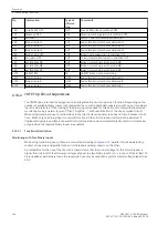
2.14.2.2
2.14.2.3
2.14.2.4
Functions
2.14 Monitoring Functions
SIPROTEC 4, 7SD80, Manual
165
E50417-G1100-C474-A2, Edition 02.2018
Summary of Contents for SIPROTEC 4 7SD80
Page 8: ...8 SIPROTEC 4 7SD80 Manual E50417 G1100 C474 A2 Edition 02 2018 ...
Page 10: ...10 SIPROTEC 4 7SD80 Manual E50417 G1100 C474 A2 Edition 02 2018 ...
Page 18: ...18 SIPROTEC 4 7SD80 Manual E50417 G1100 C474 A2 Edition 02 2018 ...
Page 248: ...248 SIPROTEC 4 7SD80 Manual E50417 G1100 C474 A2 Edition 02 2018 ...
Page 298: ...298 SIPROTEC 4 7SD80 Manual E50417 G1100 C474 A2 Edition 02 2018 ...
Page 312: ...312 SIPROTEC 4 7SD80 Manual E50417 G1100 C474 A2 Edition 02 2018 ...
Page 322: ...322 SIPROTEC 4 7SD80 Manual E50417 G1100 C474 A2 Edition 02 2018 ...
Page 400: ...400 SIPROTEC 4 7SD80 Manual E50417 G1100 C474 A2 Edition 02 2018 ...
Page 402: ...402 SIPROTEC 4 7SD80 Manual E50417 G1100 C474 A2 Edition 02 2018 ...

