Application Scope
The digital Line Differential Protection SIPROTEC 4 7SD80 is a selective short-circuit protection for overhead
lines and cables with single- and multi-ended infeeds in radial, ring or any type of meshed systems of any
transmission level. The measured data are compared separately for each phase.
A major advantage of the differential protection principle is the instantaneous tripping in the event of a short
circuit at any point within the entire protected zone. The current transformers limit the protected zone at the
ends towards the remaining system. This rigid delimitation is the reason why the differential protection
scheme shows such an ideal selectivity.
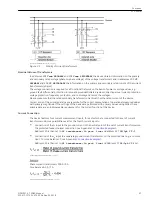
The differential protection system requires a 7SD80 device as well as a set of current transformers at either
end of the protected zone. Voltage transformers are not required for the differential protection functions in
the 7SD80; they are, however, available to record and display measured values (voltages, power, power
factor) or when using a directional overcurrent protection element.
The devices located at the ends of the protected zone exchange measuring information via protection inter-
faces using communication links (usually optical fiber or copper cables).
Since fault-free data transmission is the prerequisite for the proper operation of the protection, it is continu-
ously monitored internally.
Protection Functions
The device's basic function is to detect short-circuits or ground faults in the protected zone – even weak-
current or high-resistance short-circuits. Even complex multiphase faults are detected correctly, as the meas-
ured values are evaluated separately for each phase. The protection is restraint against inrush currents of
power transformers. When switching a line onto a fault, it is possible to send an instantaneous trip signal. The
7SD80 line differential protection includes the differential protection functions of phase comparison protec-
tion and ground fault differential protection. Both differential protection functions operate independently of
each other.
In the event of a communication failure, the devices can automatically switch to emergency operation using
an integrated overcurrent protection until communication is restored. The overcurrent protection comprises
two definite time-overcurrent protection elements and one inverse time-overcurrent protection element. Both
elements operate directional or non-directional. Additionally, the device features a third definite time-overcur-
rent protection element that always operates non-directionally.
For inverse time overcurrent protection, several characteristic curves of different standards are available.
Alternatively, the time overcurrent protection can be used as a backup time overcurrent protection, i.e. it oper-
ates independent of and parallel to the differential protection at either end.
The communication link can be used for transmitting further information. Besides measured values, it is
possible to transmit binary information.
All protection functions in the 7SD80 always trip 3-pole. They can work together with an integrated automatic
reclose function (optional). The automatic reclose functions enables 3-pole automatic reclosing with two
reclose attempts.
The thermal overload protection protects cables and power transformers from inadmissible heating due to
overload.
Additionally, a two-element overvoltage and undervoltage protection and a four-element frequency protec-
tion can be used. A circuit-breaker failure protection monitors the response of the circuit breaker following a
trip command.
Control Functions
The device provides a control function which can be accomplished for activating and deactivating switchgear
via operator buttons, port B, binary inputs and - using a PC and the DIGSI software - via the front interface.
The switch positions are fed back to the device via auxiliary contacts of the circuit breakers and binary inputs.
The current switch positions can be read out at the device and used for plausibility monitoring and interlock-
ings. The number of the devices to be switched is limited by the binary inputs and outputs available in the
device or the binary inputs and outputs allocated for the switch position feedbacks. Depending on the equip-
ment, one binary input (single point indication) or two binary inputs (double point indication) can be used.
The release to switch can be restricted by appropriate settings for the switching authority (remote or local),
and by the operating mode (interlocked/non-interlocked, with or without password validation). Interlocking
1.2
Introduction
1.2 Application Scope
SIPROTEC 4, 7SD80, Manual
23
E50417-G1100-C474-A2, Edition 02.2018
Summary of Contents for SIPROTEC 4 7SD80
Page 8: ...8 SIPROTEC 4 7SD80 Manual E50417 G1100 C474 A2 Edition 02 2018 ...
Page 10: ...10 SIPROTEC 4 7SD80 Manual E50417 G1100 C474 A2 Edition 02 2018 ...
Page 18: ...18 SIPROTEC 4 7SD80 Manual E50417 G1100 C474 A2 Edition 02 2018 ...
Page 248: ...248 SIPROTEC 4 7SD80 Manual E50417 G1100 C474 A2 Edition 02 2018 ...
Page 298: ...298 SIPROTEC 4 7SD80 Manual E50417 G1100 C474 A2 Edition 02 2018 ...
Page 312: ...312 SIPROTEC 4 7SD80 Manual E50417 G1100 C474 A2 Edition 02 2018 ...
Page 322: ...322 SIPROTEC 4 7SD80 Manual E50417 G1100 C474 A2 Edition 02 2018 ...
Page 400: ...400 SIPROTEC 4 7SD80 Manual E50417 G1100 C474 A2 Edition 02 2018 ...
Page 402: ...402 SIPROTEC 4 7SD80 Manual E50417 G1100 C474 A2 Edition 02 2018 ...

