•
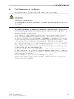
Check now the Event Log or in the spontaneous annunciations of the device where you are working:
–
Indication no. 3243
PDI FO con. to.
(protection interface connected with).
–
If the parameterization of the devices is consistent, i.e. the requirements have been observed when
setting the Functional Scope (Section
), the Power System Data 1
), the Protection Interface
), the fault indication for the verified interface also disap-
pears, i.e. no. 3230
PDI FO faulty
or no. 3232
PDI Cu faulty
. The communication and
consistency check has thus been completed.
Availability of the Protection Data Interfaces
The quality of protection data transmission depends on the availability of the protection data interfaces and
the transmission. Therefore, check the statistic information of the device.
Check the following information:
•
Indication no. 7753
FO A/m
(availability per minute) and indication no. 7754
FO A/h
(availability per
hour) indicate the availability of protection data interface 1. The value of no. 7753
FO A/m
should attain
a minimum availability of 99.85% after two minutes of operation. The value of no. 7754
FO A/h
should
attain a minimum availability of 99.85% after one hour of operation.
If these values are not attained, the protection communication should be checked.
Checking Circuit Breaker Failure Protection
General
If the device provides a breaker failure protection and if this is used, the integration of this protection function
in the system must be tested under practical conditions.
Due to the variety of application options and the available system configurations, it is not possible to make a
detailed description of the necessary tests. It is important to observe local conditions and protection and
system drawings.
Before starting the circuit breaker tests it is recommended to isolate the circuit breaker of the tested feeder at
both ends, i.e. line isolators and busbar isolators should be open so that the breaker can be operated without
risk.
!
CAUTION
Also for tests on the local circuit breaker of the feeder a trip command to the surrounding circuit breakers
can be issued for the busbar.
Non–observance of the following measure can result in minor personal injury or property damage.
²
Therefore, primarily it is recommended to interrupt the tripping commands to the adjacent (busbar)
breakers, e.g. by interrupting the corresponding pickup voltages.
Before the breaker is finally closed for normal operation, the trip command of the feeder protection routed to
the circuit breaker must be disconnected so that the trip command can only be initiated by the breaker failure
protection.
Although the following lists do not claim to be complete, they may also contain points which are to be ignored
in the current application.
Auxiliary Contacts of the CB
The circuit breaker auxiliary contact(s) form an essential part of the breaker failure protection system in case
they have been connected to the device. Make sure the correct assignment has been checked.
3.3.7
Mounting and Commissioning
3.3 Commissioning
238
SIPROTEC 4, 7SD80, Manual
E50417-G1100-C474-A2, Edition 02.2018
Summary of Contents for SIPROTEC 4 7SD80
Page 8: ...8 SIPROTEC 4 7SD80 Manual E50417 G1100 C474 A2 Edition 02 2018 ...
Page 10: ...10 SIPROTEC 4 7SD80 Manual E50417 G1100 C474 A2 Edition 02 2018 ...
Page 18: ...18 SIPROTEC 4 7SD80 Manual E50417 G1100 C474 A2 Edition 02 2018 ...
Page 248: ...248 SIPROTEC 4 7SD80 Manual E50417 G1100 C474 A2 Edition 02 2018 ...
Page 298: ...298 SIPROTEC 4 7SD80 Manual E50417 G1100 C474 A2 Edition 02 2018 ...
Page 312: ...312 SIPROTEC 4 7SD80 Manual E50417 G1100 C474 A2 Edition 02 2018 ...
Page 322: ...322 SIPROTEC 4 7SD80 Manual E50417 G1100 C474 A2 Edition 02 2018 ...
Page 400: ...400 SIPROTEC 4 7SD80 Manual E50417 G1100 C474 A2 Edition 02 2018 ...
Page 402: ...402 SIPROTEC 4 7SD80 Manual E50417 G1100 C474 A2 Edition 02 2018 ...

