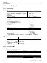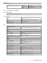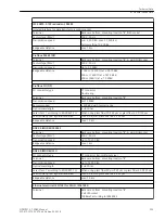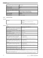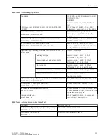
Test voltage (with regard to the socket)
(PELV)
500 V; 50 Hz
Transmission speed
100 MBit/s
Bridgeable distance
20 m
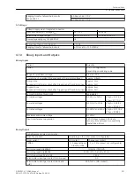
Ethernet optical (EN 100) for DIGSI, IEC61850
Terminal
Back case bottom, mounting location "B”,
Duplex-LC, 100BaseF according to IEEE802.3
Transmission speed
100 MBit/s
Optical wavelength
1300 nm
Bridgeable distance
max. 2 km (1.24 mi)
Electrical Tests
Standards
Standards:
IEC 60255
IEEE Std C37.90, see individual functions
VDE 0435
for more standards see also individual functions
Insulation Tests
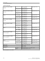
Normen:
IEC 60255-27 and IEC 60870-2-1
High voltage test (routine test). All circuits except
power supply, binary inputs, communication inter-
faces and CU protection data interface
2.5 kV, 50 Hz
High voltage test (routine test). Auxiliary voltage
and binary inputs
DC 3.5 kV
High voltage test (routine test): isolated communi-
cation interfaces (A and B)
500 V, 50 Hz
Voltage test (routine test) CU protection data inter-
face
1)
DC 70 V
Impulse voltage test (type test), all processor
circuits against each other and against the
grounding terminal (except communication inter-
face and CU protection data interface) category III
5 kV (peak value);
1.2 µs/50 µs; 0.5 J;
3 positive and 3 negative impulses at intervals of 1 s
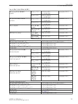
Impulse voltage test (type test), all processor
circuits against the internal electronics (except
communication interface and CU protection data
interface)
6 kV (peak value);
1.2 µs/50 µs; 0.5 J;
3 positive and 3 negative impulses at intervals of 1 s
Impulse voltage test (type test), all processor
circuits against the CU protection data interface
2)
6 kV (peak value);
1.2 µs/50 µs; 0.5 J;
3 positive and 3 negative impulses at intervals of 1 s
Voltage test (type test) only CU protection data
interface against all processor circuits
2)
DC 3.5 kV
Voltage test (type test) only CU protection data
interface against protective grounding terminal
3)
1.9 kV, 50 Hz
1)
Protection circuits through surge arresters on the primary side
2)
(type test) not against protective conductor and internal electronic components. Protection circuits through
surge arresters on the primary side
3)
Voltage test without surge arresters (only type test), see also Section 3.1 Mounting and Connections
4.1.5
Technical Data
4.1 General Device Data
254
SIPROTEC 4, 7SD80, Manual
E50417-G1100-C474-A2, Edition 02.2018
Summary of Contents for SIPROTEC 4 7SD80
Page 8: ...8 SIPROTEC 4 7SD80 Manual E50417 G1100 C474 A2 Edition 02 2018 ...
Page 10: ...10 SIPROTEC 4 7SD80 Manual E50417 G1100 C474 A2 Edition 02 2018 ...
Page 18: ...18 SIPROTEC 4 7SD80 Manual E50417 G1100 C474 A2 Edition 02 2018 ...
Page 248: ...248 SIPROTEC 4 7SD80 Manual E50417 G1100 C474 A2 Edition 02 2018 ...
Page 298: ...298 SIPROTEC 4 7SD80 Manual E50417 G1100 C474 A2 Edition 02 2018 ...
Page 312: ...312 SIPROTEC 4 7SD80 Manual E50417 G1100 C474 A2 Edition 02 2018 ...
Page 322: ...322 SIPROTEC 4 7SD80 Manual E50417 G1100 C474 A2 Edition 02 2018 ...
Page 400: ...400 SIPROTEC 4 7SD80 Manual E50417 G1100 C474 A2 Edition 02 2018 ...
Page 402: ...402 SIPROTEC 4 7SD80 Manual E50417 G1100 C474 A2 Edition 02 2018 ...

