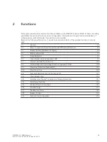


Functional Description
The data of a fault event can be read out via the device interface and evaluated with the help of the SIGRA 4
graphic analysis software. SIGRA 4 graphically represents the data recorded during the fault event and also
calculates additional information from the measured values. Currents and voltages can be presented either as
primary or as secondary values. Signals are additionally recorded as binary tracks (marks) e.g. "pickup", "trip".
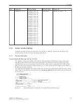
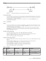
If port B of the device has been configured correspondingly, the fault record data can be imported by a central
controller via this interface and evaluated. Currents and voltages are prepared for a graphic representation.
Signals are additionally recorded as binary tracks (marks) e.g. "pickup", "trip".
The retrieval of the fault data by the central controller takes place automatically either after each protection
pickup or after a tipping.
i
i
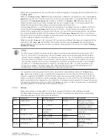
NOTE
The signals used for the binary tracks can be allocated in DIGSI.
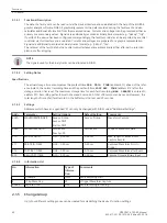
Setting Notes
Specifications
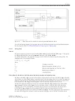
The actual storage time encompasses the pre-fault time
PRE. TRIG. TIME
(address 411) ahead of the refer-
ence instant, the normal recording time and the post-fault time
POST REC. TIME
(address 412) after the
storage criterion has reset. The maximum storage time for each fault recording (
MAX. LENGTH
) is entered in
address 410. Recording per fault must not exceed 5 seconds. A total of 8 records can be saved. However, the
total length of time of all fault records in the buffer must not exceed 25 seconds.
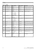
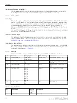
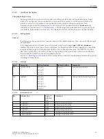
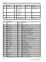
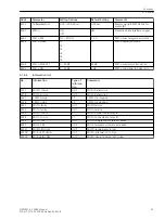
Settings
Addresses which have an appended “A” can only be changed with DIGSI, under “Additional Settings”.
Addr.
Parameter
Setting Options
Default Setting
Comments
402A
WAVEFORMTRIGGER
Save w. Pickup
Save w. TRIP
Start w. TRIP
Save w. Pickup
Waveform Capture
403A
WAVEFORM DATA
Fault event
Pow.Sys.Flt.
Fault event
Scope of Waveform Data
410
MAX. LENGTH
0.30 .. 5.00 sec
2.00 sec
Max. length of a Waveform
Capture Record
411
PRE. TRIG. TIME
0.05 .. 0.50 sec
0.25 sec
Captured Waveform Prior to
Trigger
412
POST REC. TIME
0.05 .. 0.50 sec
0.10 sec
Captured Waveform after Event
415
BinIn CAPT.TIME
0.10 .. 5.00 sec
0.50 sec
Capture Time via Binary Input
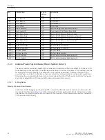
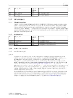
Information List
No.
Information
Type of
Informa-
tion
Comments
-
FltRecSta
IntSP
Fault Recording Start
4
>Trig.Wave.Cap.
SP
>Trigger Waveform Capture
30053
Fault rec. run.
OUT
Fault recording is running
Change Group
Up to four different setting groups can be created for establishing the device's function settings.
2.1.4.1
2.1.4.2
2.1.4.3
2.1.4.4
2.1.5
Functions
2.1 General
40
SIPROTEC 4, 7SD80, Manual
E50417-G1100-C474-A2, Edition 02.2018
Summary of Contents for SIPROTEC 4 7SD80
Page 8: ...8 SIPROTEC 4 7SD80 Manual E50417 G1100 C474 A2 Edition 02 2018 ...
Page 10: ...10 SIPROTEC 4 7SD80 Manual E50417 G1100 C474 A2 Edition 02 2018 ...
Page 18: ...18 SIPROTEC 4 7SD80 Manual E50417 G1100 C474 A2 Edition 02 2018 ...
Page 248: ...248 SIPROTEC 4 7SD80 Manual E50417 G1100 C474 A2 Edition 02 2018 ...
Page 298: ...298 SIPROTEC 4 7SD80 Manual E50417 G1100 C474 A2 Edition 02 2018 ...
Page 312: ...312 SIPROTEC 4 7SD80 Manual E50417 G1100 C474 A2 Edition 02 2018 ...
Page 322: ...322 SIPROTEC 4 7SD80 Manual E50417 G1100 C474 A2 Edition 02 2018 ...
Page 400: ...400 SIPROTEC 4 7SD80 Manual E50417 G1100 C474 A2 Edition 02 2018 ...
Page 402: ...402 SIPROTEC 4 7SD80 Manual E50417 G1100 C474 A2 Edition 02 2018 ...